ACH550-UH User’s Manual 1-23
Installation
The locations of screws EM1 and EM3 are shown in the diagram on page 1-20. The
locations of screws F1 and F2 are shown in the diagram on page 1-21.
Install the wiring
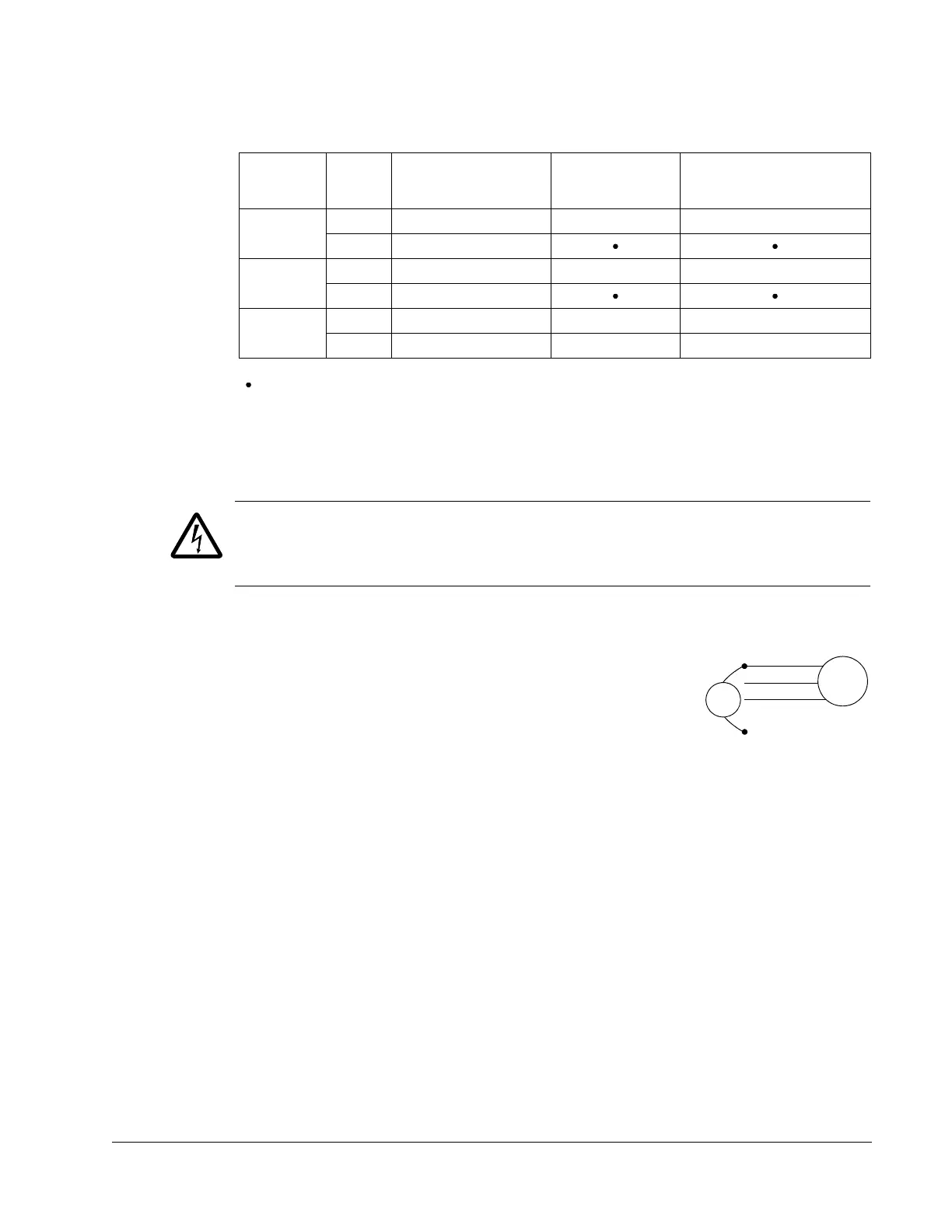
Checking motor and motor cable insulation
WARNING! Check the motor and motor cable insulation before connecting the drive
to input power. For this test, make sure that motor cables are NOT connected to the
drive.
1. Complete motor cable connections to the motor, but NOT to the drive output
terminals (U2, V2, W2).
2. At the drive end of the motor cable, measure the insulation
resistance between each motor cable phase and Protective
Earth (PE): Apply a voltage of 1 kV DC and verify that
resistance is greater than 1 Mohm.
Frame
sizes
Screw
Symmetrically
grounded TN systems
(TN-S systems)
Corner grounded
TN systems
IT systems (ungrounded
or high-resistance-
grounded [> 30 ohm])
R1…R3
EM1 x x –
EM3 x
R4
EM1 x x –
EM3 x
R5…R6
F1 x x –
F2 x x –
x = Use the provided metal screw which may already be installed. (EMC filter(s) will be connected.)
= Use the installed polyamide screw. (EMC output filter will be disconnected.)
–
= Remove the installed metal screw. (EMC filter(s) will be disconnected.)

 Loading...


