ACH550-UH User’s Manual 1-309
Technical data
Motor connections
WARNING! Never connect line power to the drive output terminals: U2, V2 or W2.
Line voltage applied to the output can result in permanent damage to the unit. If
frequent bypassing is required, use mechanically interlocked switches or contactors.
WARNING! Do not connect any motor with a nominal voltage less than one half of
the drive’s nominal input voltage.
WARNING! Disconnect the drive before conducting any voltage tolerance (Hi-Pot)
test or insulation resistance (Megger) test on the motor or motor cables. Do not
conduct these tests on the drive.
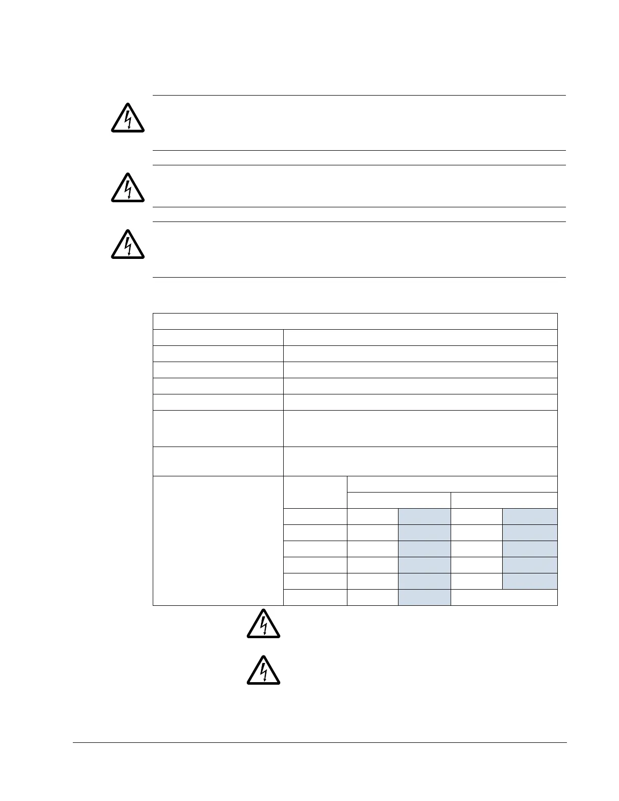
Motor connection specifications
Motor Connection Specifications
Voltage (U
2
) 0…U
1
, 3-phase symmetrical, U
max
at the field weakening point
Frequency 0…500 Hz
Frequency Resolution 0.01 Hz
Current See Ratings on page 1-297.
Field Weakening Point 10…500 Hz
Switching Frequency
Selectable: 1, 4, 8, or 12 kHz
(1, 4, or 8 kHz for 600 V, R6 frame size, that is for
ACH550-xx-077A-6 … ACH550-xx-144A-6)
Minimum Cable
Temperature Rating
60 °C (140 °F) for field wiring terminals for circuits of 100 A or less.
75 °C (167 °F) for field wiring terminals for circuits over 100 A.
Maximum Motor Cable
Length
Frame Size
Max. Motor Cable Length*
f
sw
= 1 or 4 kHz f
sw
= 8 kHz or 12 kHz
R1 100 m
330 ft 100 m 330 ft
R2 200 m
650 ft 100 m 330 ft
R3…R4 200 m
650 ft 100 m 330 ft
R5…R6 300 m
980 ft 150 m 490 ft
R6 (600 V) 100 m
330 ft 100 m 330 ft
R7…R8 300 m
980 ft Does not apply
* WARNING! Using a motor cable longer than specified in the
table above may cause permanent damage to the drive. Additional
distance may be achieved with the use of an appropriate output
filter.
* WARNING! The above table refers only to the maximum motor
cable distance that the drive can tolerate. Consult the motor
manufacturer for any limitations on the distance that the motor can
tolerate. The above table is not intended as a motor protection
guide.

 Loading...


