ACH550-UH User’s Manual 1-61
Application macros
Dual Setpoint with PID macro
This macro configures for dual setpoint PID applications, where activating digital
input 3 (DI3) changes the process PID controller’s setpoint to another value. When
using direct speed reference in AUTO mode or process PID, see General
considerations on page 1-49. Set process PID setpoints (internal to the drive) using
parameters 4011 (
SET1) and 4111 (SET2).
Parameters Changed Relative to HVAC Default
Parameter Value
Parameter Value
9902
APPLIC MACRO 11 (DUAL SETPPID) 4010 SET POINT SEL 19 (INTERNAL)
1201 CONST SPEED SEL 0 (NOT SEL) 4011 INTERNAL SETPNT 50.0%
1401
RELAY OUTPUT 17 (STARTED) 4027 PID 1 PARAM SET 3 (DI3)
1601
RUN ENABLE 2 (DI2) 4110 SET POINT SEL 19 (INTERNAL)
1609
START ENABLE 25 (DI5) 4111 INTERNAL SETPNT 100.0%
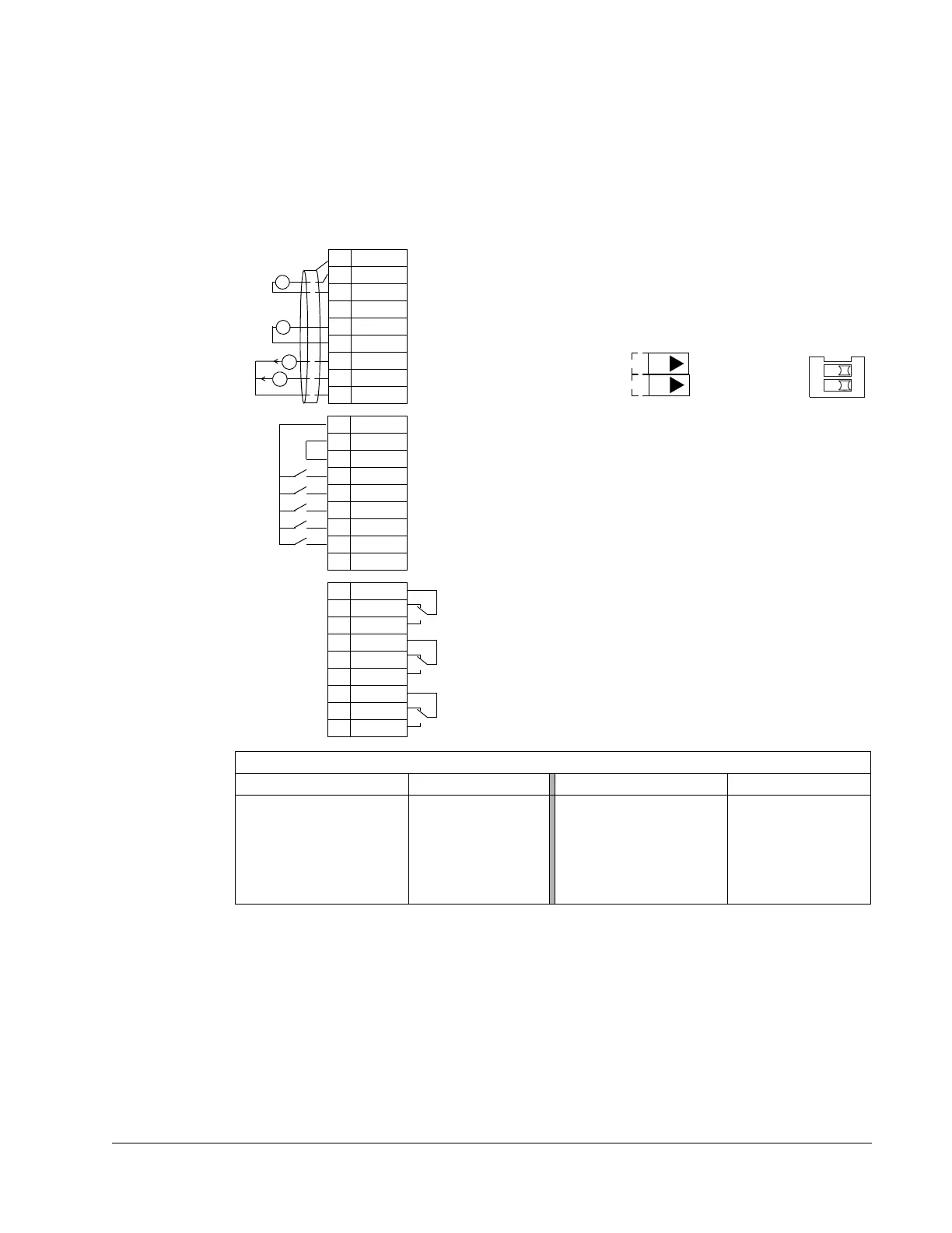
1SCR
2AI1
3AGND
410V
5AI2
6AGND
7AO1
8AO2
9AGND
10 24V
11 GND
12 DCOM
13 DI1
14 DI2
15 DI3
16 DI4
17 DI5
18 DI6
19 RO1C
20 RO1A
21 RO1B
22 RO2C
23 RO2A
24 RO2B
25 RO3C
26 RO3A
27 RO3B
X1
+
mA
mA
External reference 0(2)…10 V or 0(4)…20 mA
Reference voltage 10 VDC
Output frequency: 0(4)…20 mA
Start/Stop: Activate to start drive
Run permissive: Deactivate to stop drive (P 1601)
Setpoint selection: Activate to select Set2 (P 4207)
Safety interlock 1: Deactivate to stop drive (P 1608)
Safety interlock 2: Deactivate to stop drive (P 1609)
Relay output 1 (P 1401)
Default operation: Started =>19 connected to 21
Relay output 2 (P 1402)
Default operation: Running =>22 connected to 24
Relay output 3 (P 1403)
Default operation: Fault (-1) =>25 connected to 27
Output current: 0(4)…20 mA
Not configured
Analog input circuit common
PID feedback: 0(2)…10 V or 0(4)…20 mA
Analog output circuit common
Auxiliary voltage output +24 VDC
Common for DI return signals.
Auxiliary voltage output common
Signal cable shield (screen)
Analog input circuit common
(Fault => 25 connected to 26)
+
J1
AI1: 0(4)
…20 mA
AI2: 0(4)
…20 mA
ON
J1 Jumper Settings
ON
ON
12

 Loading...


