ACH550-UH User’s Manual 1-29
Installation
Apply power
Always re-install the covers before turning power on.
WARNING! The ACH550 will start up automatically at power up, if the external run
command is on.
1. Apply input power.
When power is applied to the ACH550, the green LED comes on.
WARNING! Even when the motor is stopped, dangerous voltage is present at the
power circuit terminals U1, V1, W1 (L1, L2, L3) and U2, V2, W2 (T1, T2, T3) and,
depending on the frame size, UDC+ and UDC-, or BRK+ and BRK-.
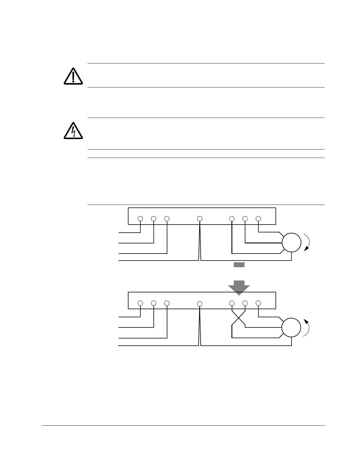
Note: Before increasing motor speed, check that the motor is running in the desired
direction. To change rotation direction, switch motor leads as shown below. Power
circuit terminal designation and location varies depending on the frame size and
some terminals are not used (UDC+ and UDC-, or BRK+ and BRK-). Refer to pages
1-20 and 1-21 for specific terminal layouts.
U1 V1 W1 U2 V2 W2
L1
L2
L3
Motor
Drive
Input
FM
U1 V1 W1 U2 V2 W2
L1
L2
L3
Motor
Drive
Input
To change rotation direction,
switch motor leads
GND
GND
GND
GND
 Loading...


