 Loading...
Do you have a question about the ABB ACS 6000 and is the answer not in the manual?
| Type | Medium Voltage AC Drive |
|---|---|
| Communication Protocols/Interface | Modbus, Profibus, Ethernet |
| Efficiency | Up to 98% |
| Voltage | 6 kV to 11 kV |
| Input Voltage | 3.3 kV to 11 kV |
| Topology | Multilevel |
| Control Type | Direct Torque Control (DTC) |
| Cooling Method | Air or Water Cooling |
| Protection Features | Overcurrent, overvoltage, undervoltage, short circuit |
| Enclosure Rating | IP54 |
| Applications | Pumps, fans, compressors, conveyors |
| Voltage Levels | 3.3 kV, 4.16 kV, 6.6 kV, 10 kV |
Overview of the manual's purpose and target audience for ACS 6000 maintenance.
Critical safety precautions, warnings, and procedures for working with high-voltage ACS 6000.
Safety measures to be followed before and during testing of IGCTs and diodes.
Procedure and tools for testing IGCT components using voltage measurements and visual checks.
Method for testing diodes within 7/9 MVA phase modules using multimeter voltage readings.
List of specialized tools required for replacing diodes and thyristors in the LSU.
Essential safety precautions for deenergizing and handling components during LSU maintenance.
Step-by-step guide for replacing diodes and thyristors in the LSU rectifier stack.
Tools needed for safely removing and installing 3/5 MVA phase modules.
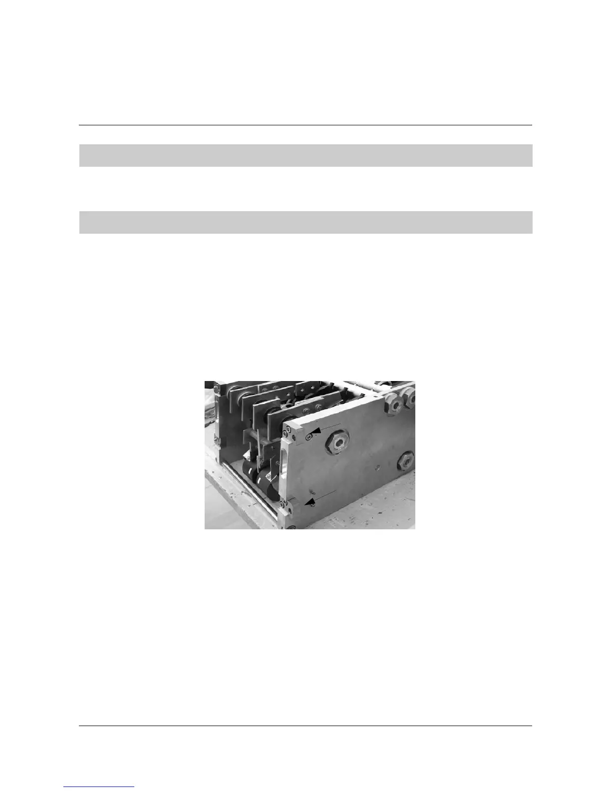
Detailed procedure for safely disconnecting and extracting a 3/5 MVA phase module from the cabinet.
Steps for correctly re-installing a 3/5 MVA phase module, including greasing and connections.
Tools and accessories needed for changing clamp diodes in 3/5 MVA phase modules.
Step-by-step instructions for removing and replacing clamp diodes in 3/5 MVA phase modules.
Tools and accessories required for changing 7/9 MVA phase modules.
Procedure for safely disconnecting and removing 7/9 MVA phase modules from the cabinet.
Steps for correctly installing a 7/9 MVA phase module, including connections and final checks.
List of tools needed for replacing diodes and IGCTs in 7/9 MVA phase modules.
General overview of semiconductor locations within the 7/9 MVA phase module.
Critical safety measures for working with 7/9 MVA phase modules.
Detailed steps for replacing clamp and NP diodes in 7/9 MVA phase modules.
Procedure for replacing free-wheeling diodes in 7/9 MVA phase modules.
Steps for replacing IGCTs within the 7/9 MVA phase module while it remains in the cabinet.
Tools required for changing thyristors in the EXU.
Safety procedures for working on the EXU, emphasizing deenergization.
Procedure for replacing thyristors in EXUs used for brushless excitation.
Procedure for replacing thyristors in EXUs used for direct excitation.
Graphical representation of deflection values for thyristor clamp forces.
Tools needed for changing semiconductors in the VLU.
Safety precautions for semiconductor replacement in the VLU.
General procedure for replacing diodes and IGCTs in the VLU semiconductor stack.
Tools needed for replacing IGCTs in the DIU.
Safety measures for working on the DIU and replacing IGCTs.
Step-by-step guide to safely remove an IGCT from the DIU.
Procedure for installing a new IGCT into the DIU, including clamping pressure adjustment.
Safety precautions for handling and replacing sensitive printed circuit boards.
Procedure for replacing an AMC3 board in the COU cabinet.
Steps to replace the flash memory PCB on an AMC3 board.
Guide for replacing INT boards located in ARU, INU, and COU cabinets.
Procedure for replacing CVMI boards in ARU and INU cabinets.
Description of LEDs and their functions on the AMC board.
Explanation of LEDs on INT boards in ARU, INU, and COU configurations.
LED functions for GUSP units, detailing operational status and faults.
LED indicators for IGCT output stage functions and potential issues.
Tightening torques for pipe couplings and pumps in the water cooling unit.
Recommended tightening torques for pipe joints and busbar connections.


