Chapter 10 - Changing Semiconductors in VLU ABB
10-2 (6) 3BHS202077 ZAB E01 Rev. C ACS 6000 Maintenance Manual
10.3.1 Preperatory Steps
1 Check that the drive has been deenergized and voltages have been
removed from the cabinet. See section
10.2 Safety
.
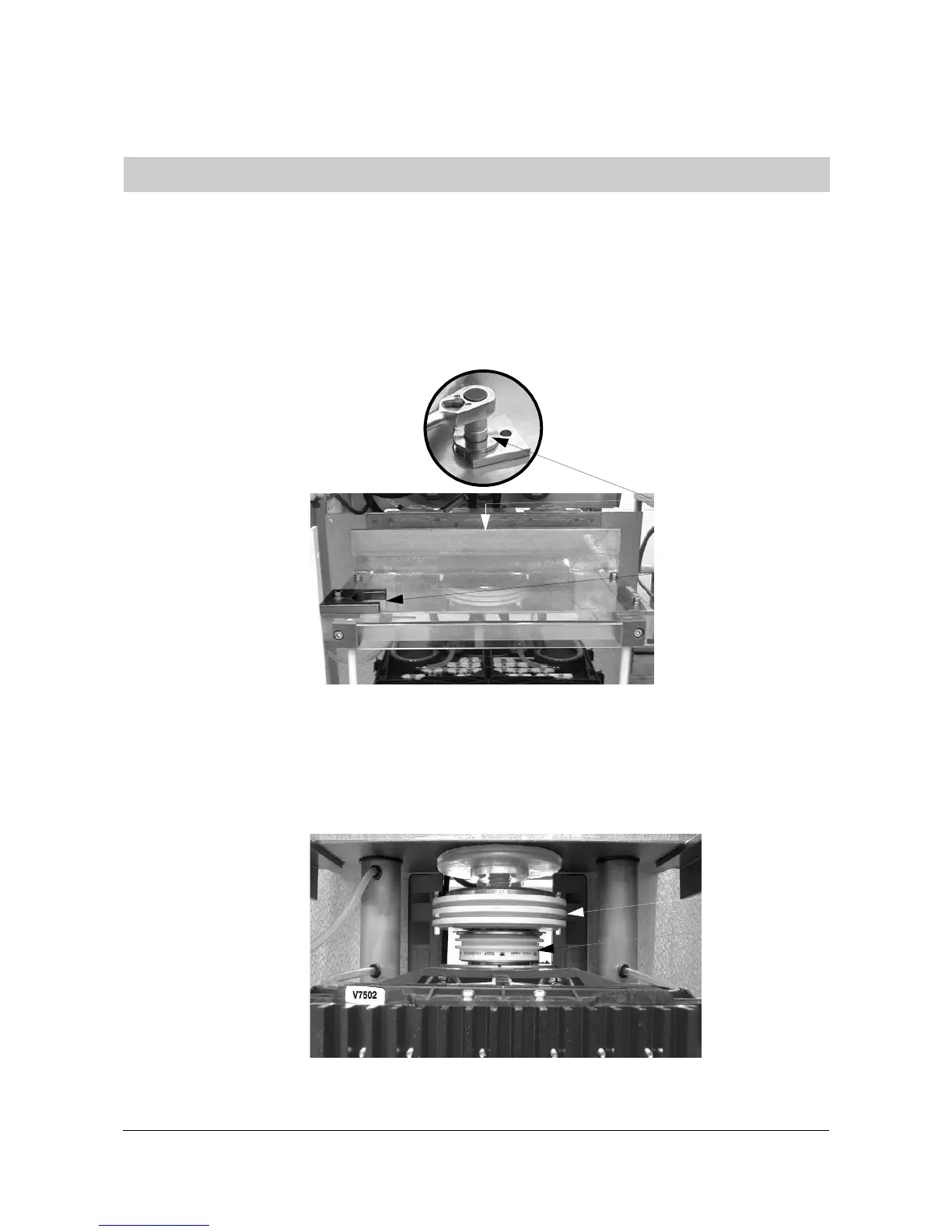
2 Slide the pressure loading gauge under the clamp ring of the
pressure adjusting bolt and remove the bolt to release the clamp
pressure of the stack using the 12 mm 1/2" hex socket from the tool
box
Figure 10-1 Top View of VLU
10.3.2 Replacing Upper Diode
In order to replace the upper diode only the clamp pressure of the stack
must be released. The retaining rods of the IGCTs (see
Figure 10-4
) can
stay in place.
Figure 10-2 Upper Diode
10.3 Replacing the Semiconductors
Pressure adjusting
bolt
Storage place of
pressure loading
gauge
Isolator disk
Upper diode
 Loading...


