Chapter 8 - Changing Diodes and IGCTs in 7/9 MVA Phase Modules ABB
8-8 (18) 3BHS202077 ZAB E01 Rev. C ACS 6000 Maintenance Manual
8.4.2 Replacing Clamp Diodes
Upper Clamp Diode
After the steps of section
8.4.1 Preparatory Steps
have been carried out
do the following:
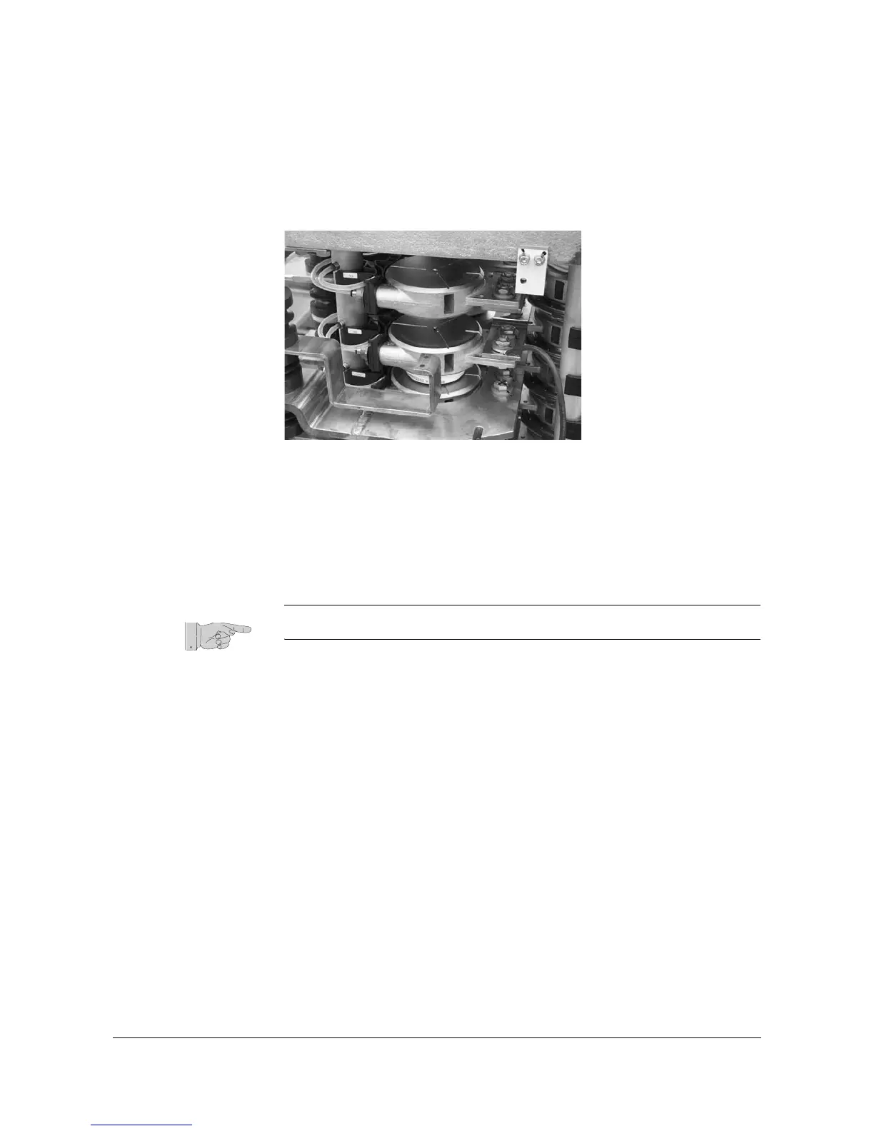
1 Remove the upper clamp diode, the isolator disc and the perforated
busbar.
Figure 8-10 Upper Clamp Diode Removed
2 Prepare the components for reassembly.
Check the contact surfaces of the new diode, the isolator disk and the
coolers for any dirt. If necessary, clean the contact surfaces with an
appropriate solvent (e. g. alcohol). Using a fluff-free cloth wipe the
surfaces paying attention not to scratch the surfaces.
Note: Do not use any grease or any electrical joint compound.
3 Put the new diode, the perforated busbar and the isolator disk on top
of each other (mind the correct order) and center them before
inserting the parts into the stack.
Pay attention to the correct polarity particularly when exchanging
diodes from different suppliers. Always verify the polarity with the
corresponding wiring diagram.
4 Insert the top isolator disk and center it.
This step must be left out if the lower clamp diode has to be replaced
as well.
5 Continue with section
Lower Clamp Diode
if the lower diode has to
replaced.
Continue with section
8.4.4 Finishing Steps
to remount the
capacitors, adjusting the clamp pressure and installing the phase
module.