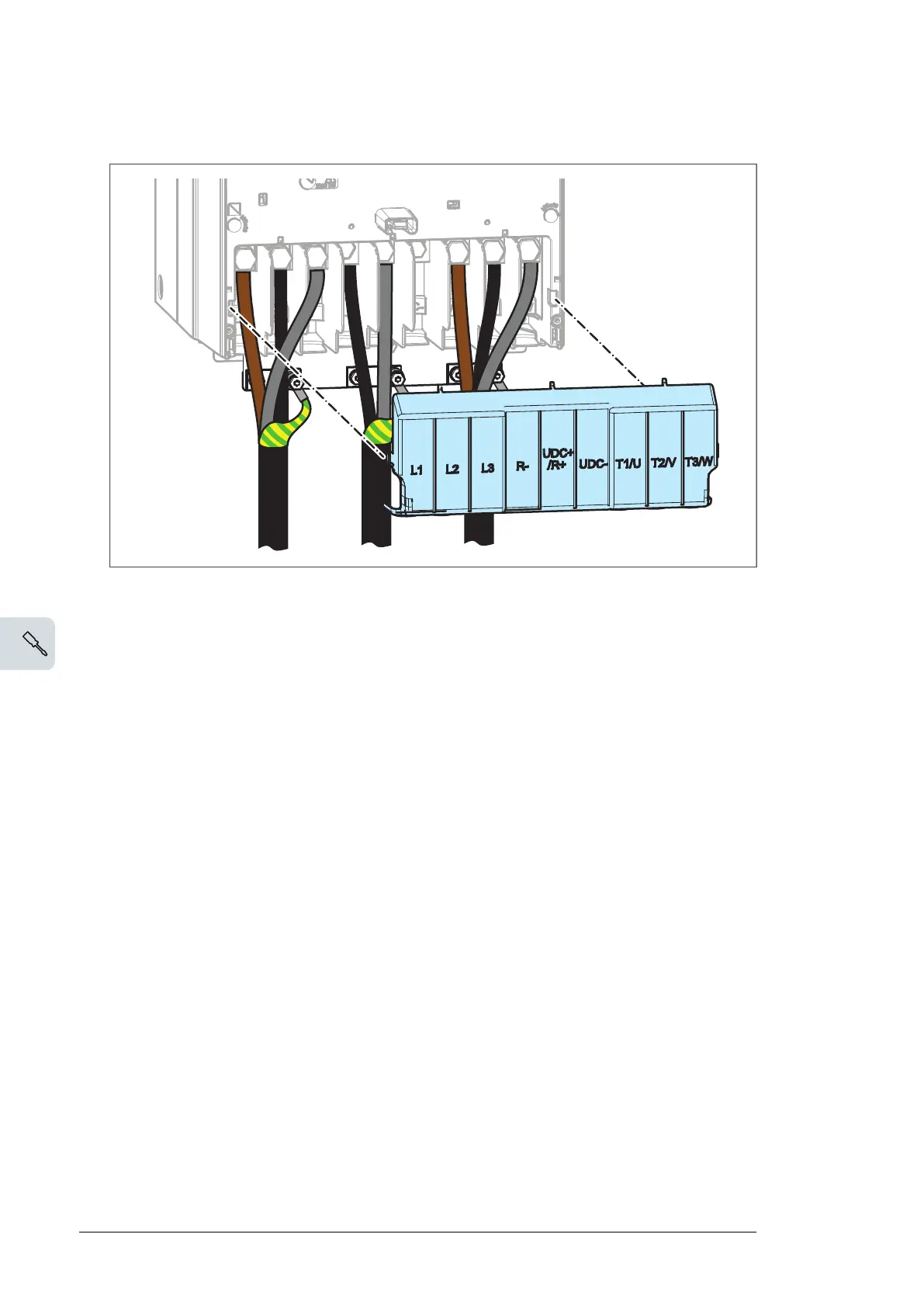
5. Reinstall the shroud on the power cable terminals
6.
Go to section Connecting the control cables – ACS880-01 frames R6 to R9 (page 50).
Connecting the control cables – ACS880-01 frames R6 to R9
1. Strip the cable ends and cut to suitable length (note the extra length of the grounding
conductors).
2. Ground the outer shields of all control cables 360 degrees at the cabinet entry.
3. Secure the cables mechanically at the clamps.
4. Ground the pair-cable shields to the clamps. Leave the other end of the shields
unconnected or ground them indirectly via a high-frequency capacitor with a few
nanofarads, eg, 3.3 nF / 630 V.
5. Connect the conductors to the appropriate terminals of the control unit (see the default
I/O connections in the hardware manual).
6. Wire the optional modules if included in the delivery.
50 Electrical installation
 Loading...