Check that …
The placement of optional modules and other equipment inside the cabinet and on the cabinet door is
correct.
The mounting of optional modules and other equipment is correct.
Internal cabling of the cabinet assembly
Main circuit:
• AC supply input cabling is ok.
• AC output cabling is ok.
• Supply for brake resistor (if used) is ok.
Cable types, cross-sections, colors and optional markings are correct.
Cabling is not susceptible to interference. Check the twisting of cables and cable routes.
Connection of cables to devices, terminal blocks and drive module circuit boards:
• Cables are connected to terminals tight enough by pulling the cable.
• Cable termination on terminals chaining is done correctly.
• Bare conductors are not too far outside the terminal causing an insufficient clearance or loss of
shielding against contact.
• The control unit is wired properly to the drive module.
• The control panel cable is connected properly.
Cables are not lying against sharp edges or bare live parts. Bending radius of fiber optic cables is at
least 3.5 cm (1.38 in).
The type, markings, insulation plates and cross connections of terminal blocks are correct.
Grounding and protection
The grounding colors, cross-section and grounding points of modules and other equipment match the
circuit diagrams. No long routes for pigtails.
Connections of PE cables and busbars are tight enough. Pull the cable to test that it does not loosen.
No long routes for pigtails.
Doors equipped with electrical equipment are grounded. No long grounding routes. From EMC standpoint
best result is achieved with a flat copper braid.
Fans that can be touched are shrouded.
Live parts inside the doors are protected against direct contact to at least IP2x.
Labels
The type designation labels and warning and instruction stickers are made according to the local regu-
lations and placed correctly.
Switches and doors
Mechanical switches, main disconnecting switch and cabinet doors function properly.
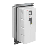
Installation of the cabinet
The drive cabinet has been attached to floor and also from top to the wall or roof.
The ambient operating conditions agree with the specifications given in chapter Technical data.
The cooling air will flow freely in and out of the drive cabinet, and air recirculation inside the cabinet
will not be possible (air baffle plates are on place).
If the drive module has been stored over one year: The electrolytic DC capacitors in the DC link of the
drive have been reformed.
There is an adequately sized protective ground conductor between the drive and the switchboard.
There is an adequately sized protective earth ground conductor between the motor and the drive.
All protective ground conductors have been connected to the appropriate terminals and the terminals
have been tightened. (Pull the conductors to check.)
The enclosures of the equipment in the cabinet have proper galvanic connection to the cabinet protective
earth (ground) busbar; The connection surfaces at the fastening points are bare (unpainted) and the
connections are tight, or separate grounding conductors have been installed.
52 Installation checklist

 Loading...