EasyManua.ls Logo

ABB ACSM1 Control Panel User Manual

ABB ACSM1 Control Panel
46 pages
To Next Page IconTo Next Page
To Previous Page IconTo Previous Page
Page #27 background imageLoading...
Page #27 background image
Operation
27
How to change the value of bit pointer parameter to point to the value of a bit
in another signal
The bit pointer parameter points to the value of a bit in another signal, or can be fixed
to 0 (FALSE) or 1 (TRUE). For the latter option, see page 29. The bit pointer
parameter points to a bit value (0 or 1) of one bit in a 32-bit signal. The first bit from
the left is bit number 31, and the first bit from the right is bit number 0. E.g. bit 01
stands for bit number 2
1
= 2, the second bit from the right, and number 00 stands for
bit number 2
0
= 1, the first bit from the right.
When adjusting a bit pointer parameter on the control panel, POINTER is selected to
define a source from another signal. A pointer value is given in format P.xx.yy.zz,
where xx = Parameter group; yy = Parameter index, zz = Bit number.
For more information, see appropriate Firmware Manual.
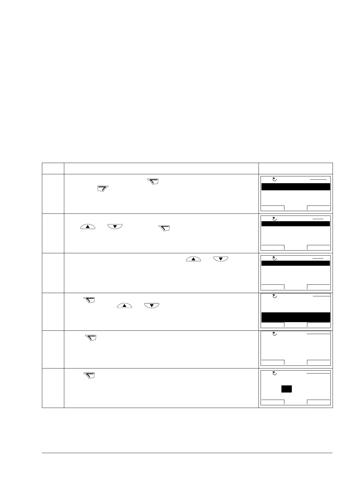
Step Action Display
1. Go to the Main menu by pressing if you are in the Output mode, otherwise
by pressing repeatedly until you get to the Main menu.
2. Go to the Parameters option by selecting PARAMETERS on the menu with
keys and , and pressing .
3. Select the appropriate parameter group with keys and . Here the
bit pointer parameter 12.04 DI01 OUT PTR is used as an example.
4.
Press to select the appropriate parameter group. Select the appropriate
parameter with keys and . Current value of each parameter is
shown below its name.
5. Press .
6. Press . Current value of the bit pointer parameter is shown, as well as the
parameter group it points to.
MENU
EXIT
PARAMETERS
FAULT LOGGER
TIME & DATE
EXIT ENTER
00:00
MAIN MENU 1
LOC
ENTER
01 ACTUAL VALUES
02 I/O VALUES
03 CONTROL VALUES
04 POS CTRL VALUES
06 DRIVE STATUS
EXIT
SEL
00:00
PAR GROUPS 01
LOC
12 DIGITAL IO
13 ANALOGUE INPUTS
15 ANALOGUE OUTPUTS
16 SYSTEM
17 PANEL DISPLAY
EXIT
SEL
00:00
PAR GROUPS 12
LOC
SEL
1201 DI01 CONF9901
1202 DI02 CONF
1203 DI03 CONF
1204 DI01 OUT PTR
P.01.01.00
PARAMETERS
EXIT
EDIT00:00
LOC
EDIT
1204 DI01 OUT PTR
PAR EDIT
Pointer
CANCEL NEXT00:00
LOC
NEXT
1204 DI01 OUT PTR
PAR EDIT
P.01.01.00
CANCEL NEXT00:00
01 ACTUAL VALUES
LOC

Table of Contents

Question and Answer IconNeed help?

Do you have a question about the ABB ACSM1 Control Panel and is the answer not in the manual?

ABB ACSM1 Control Panel Specifications

General IconGeneral
BrandABB
ModelACSM1 Control Panel
CategoryControl Panel
LanguageEnglish

Summary

About the manual

Manual Scope and Audience

Describes chapter content, compatibility, intended audience, and contact methods.

Safety Information

Details essential safety precautions and warnings for the drive.

Product Support and Training

Information on obtaining product support, training, and providing feedback.

Hardware description

Control Panel Overview and Compatibility

Explains the function of control panels for ACSM1 and their compatibility.

ACSM1 Control Panel Features and Operation

Details the features, layout, and maintenance of the ACSM1 Control Panel.

Status line information

Describes the basic status information shown on the top line of the LCD display.

Installation

Connection Procedure

Explains how to connect the control panel to the drive and the required cable.

Mounting the Control Panel

Details panel mounting kits, accessories, and installation instructions.

Mounting Template

Provides a diagram and dimensions for the panel mounting template.

Gasket Specification

Details the gasket used for panel mounting.

Operation

Basics of Operation

Explains panel operation using menus, keys, and modes.

List of Common Tasks

Presents a table of common tasks and their corresponding instructions.

Help and Panel Version

Guides on accessing help and finding panel version information.

Basic Control Functions

Details starting, stopping, and mode switching.

Output Mode Operations

Covers changing motor rotation direction and other output mode operations.

Signal Monitoring

Explains how to select signals monitored in the Output mode.

Output Mode Settings

Covers setting references and adjusting display contrast.

Parameter Management

Guides on selecting parameters and changing their values.

Value Pointer Parameters

Explains how to change the value of parameters that point to other parameters/signals.

Bit Pointer Parameters

Guides on changing bit pointer parameters to reference bits in other signals.

Fixed Bit Pointer Values

Details how to set bit pointer parameters to fixed TRUE or FALSE values.

Fault Logging and Reset

Explains how to view the drive fault history and reset faults.

Time and Date Configuration

Covers clock visibility, formats, setting date/time, and daylight saving.

Parameter Backup and Restore

Parameter Backup Overview

Explains exporting and backing up drive parameters.

Backup and Restore Procedures

Details the step-by-step procedures for backing up and restoring parameters.

Version Compatibility for Parameter Restore

Addresses issues when restoring parameters between different product variants.

Parameter Error Handling

Describes how the panel displays and handles parameter errors during operations.

User Set Restore with Firmware Mismatches

Covers restoring user sets when firmware versions differ.

User Set Load with Firmware Mismatches

Details loading user sets when firmware versions differ.

Viewing Backup Information

Explains how to view information about the stored backup file.

Reference Edit

Reference Editing Procedure

Guides on accurately controlling the local reference value and editing process.

Drive Info

Viewing Drive Information

Guides on viewing drive-specific information like name, type, and firmware.

Related product manuals