62 Product manual - PVS-175-TL;A.1 Version
EN
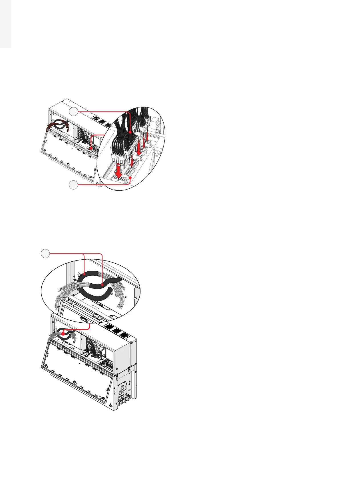
5.4.7 Connection of the interface signal connectors
The interface signal connectors (male) (35) are situated into right side of power module and they are
composed by 8 connectors.
•
Connect all the interface signal connectors (35) with the related interface signal connectors (female)
(32) (push the connector until you hear a locking “click”).
All connectors have a different pin-out in order to avoid any connection error.
32
35
5.4.8 Connection of the DC interface cables
The DC interface cables (33) are situated into left side of Power module and they are divided in two group.
33
 Loading...


