Electrical installation 43
DC input cable connection procedure
Refer to the dimension drawings in the PVS800-57B central inverters hardware manual
(3AXD50000048300 [EN]).
1. Remove the shroud from the input power terminals.
2. Put the cable(s) into the inside of the cabinet.
3. If it is a shielded cable, connect the shield to the cabinet grounding busbar with a cable
lug.
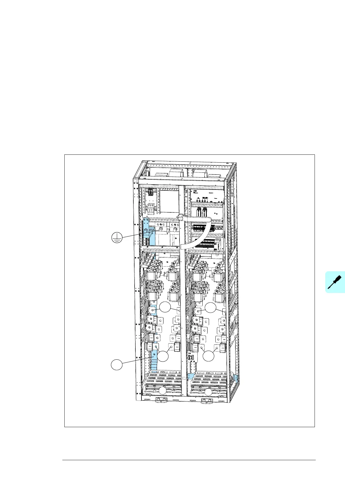
4. Connect the DC- conductor to terminal DC- and the DC+ conductor to terminal DC+.
5. If there is a separate PE conductor, connect it to the cabinet grounding terminal.
6. Refit the shroud onto the input power terminals.
DC input terminals DC-, DC +
a) Cable lead-throughs
a
DC-
DC+
a
DC+
DC-
PE
 Loading...


