46 Electrical installation
Connecting the control cables
Default I/O connection diagram
You can freely configure the I/O signals with different fault names and reactions. Refer to
the PVS800-57B central inverters firmware manual (3AXD50000048332 [EN]).
Connection procedure
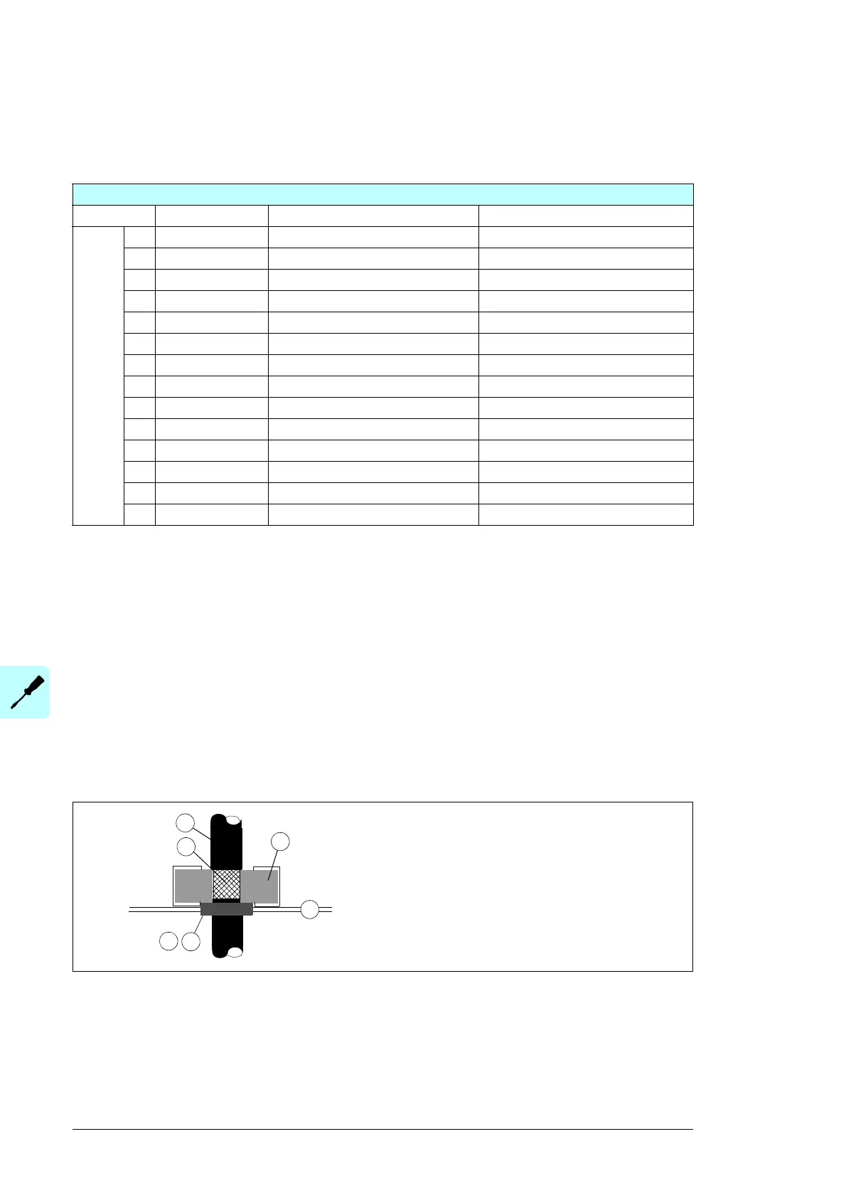
360-degree grounding at the cabinet lead-through for the control cables:
Make sure that a proper environmental seal remains after the installation.
1. Cut adequate holes in the rubber grommets in the lead-through plate.
2. Put the cables through the grommets into the cabinet.
3. Strip the plastic sheath of the cable above the lead-through plate just enough to
ensure proper connection of the bare shield.
Note: If the outer surface of the shield is non-conductive:
• Cut the shield at the midpoint of the bare part. Do not cut the conductors or the
grounding wire (if present).
• Turn the shield inside out to expose its conductive surface.
• Cover the turned shield and the stripped cable with copper foil to make the shielding
continuous.
Control I/O connection diagram
Terminal Type Rating Functionality
X2
+ +24 V DC +24 V DC Power distribution
- 0 V DC 0 V DC Power distribution
1 User DI1 24 V DC
2 User DI2 24 V DC
3 User DI3 24 V DC
4 User DI4 24 V DC
5 User DI5 24 V DC
6 User DI6 24 V DC
7 User DI7 24 V DC
8 User RO1 24 V DC
9User AI2 +
10 User AI2 4–20 mA -
11 User AI3 +
12 User AI3 4–20 mA -
a
1
3
Side view of the cable lead-through
a) Grommet
b) EMI conductive cushion
c) Lead-through plate
c
b
2
 Loading...


