40 Planning the electrical installation
Routing the cables
Install the DC power cable, output AC power cable and the control cabling on separate
routes. The cable trays must have good electrical bonding to each other and to the
grounding electrodes.
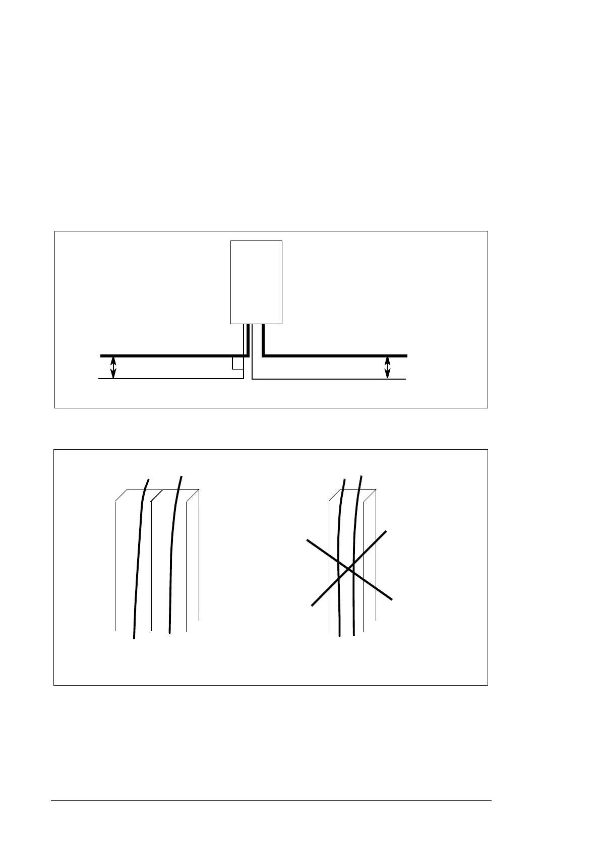
Where control cables cross power cables, make sure that you set them at an angle as
near to 90 degrees as possible. Do not run additional cables through the inverter.
If four conductor AC cabling is used, install the three output phase cables symmetrically
and close to each other. Asymmetrical installation may induce current to grounding cables
and metal structures.
Separate control cable ducts
90°
DC input cable
AC output power cable
Control cables
min. 500 mm (19.7 in.)
Inverter
min. 500 mm (19.7 in.)
24 V
24 V
230 V
Lead 24 V and 230 V (120 V) control
cables in separate ducts inside the cabinet.
Not allowed unless the 24 V cable is
insulated for 230 V (120 V) or insulated with
an insulation sleeving for 230 V (120 V).
(120 V)
230 V
(120 V)
 Loading...


