80 Control unit
Default I/O connection table
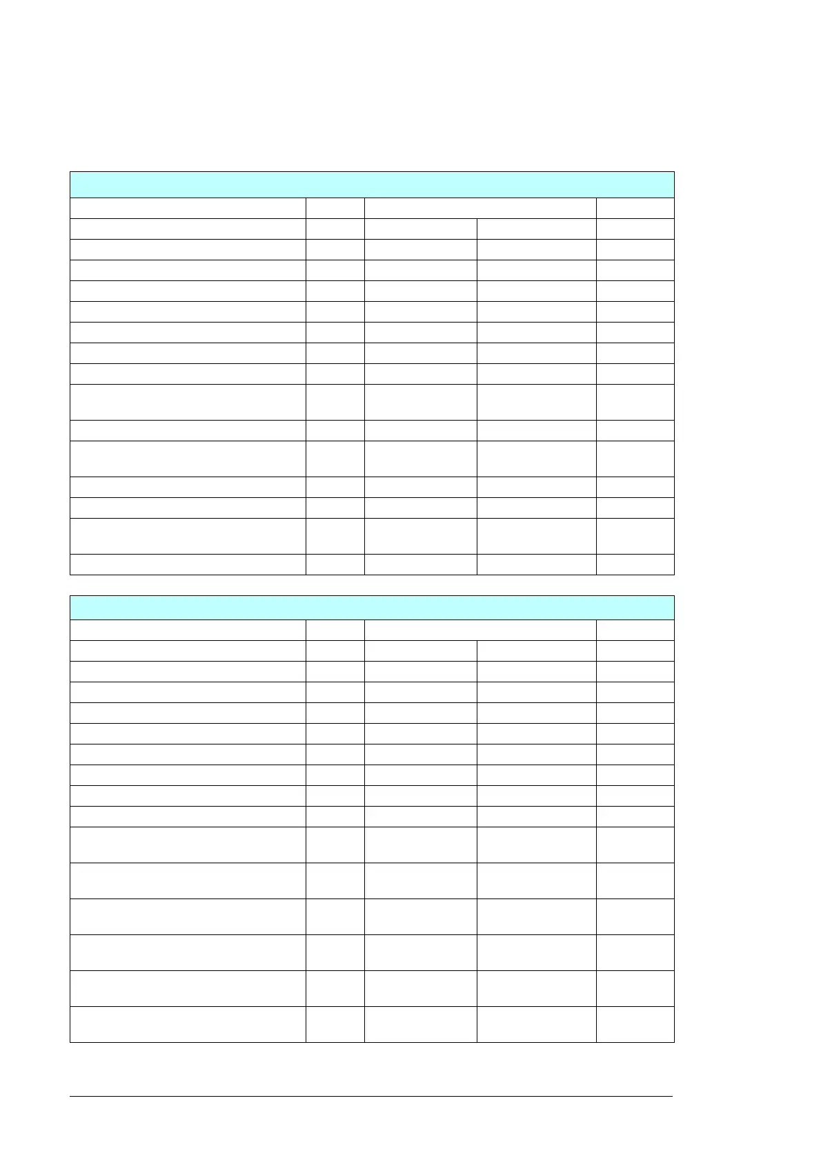
The default I/O connections of the BCU-12 control unit and the AC500 modules.
BCU-12 (A41)
Signal name Optional Interface type I/O terminal
#1 GROUND IMPEDANCE Analog input 4…20 mA AI1
#1 GROUNDING CURRENT X Analog input 4…20 mA AI2
M1 CABINET FAN SPEED REFERENCE Analog output 4…20 mA AO1
M2 CABINET FAN SPEED REFERENCE Analog output 4…20 mA AO2
START/STOP STATUS Digital input 24 V DC DI1
FPO STATUS Digital input 24 V DC DI2
#1 GROUNDING FUSE STATUS X Digital input 24 V DC DI3
24V BUFFERS READY Digital input 24 V DC DI4
M1 AUX. PROTECTION DEVICES
STATUS
Digital input 24 V DC DI5
M1 LCL CAP. PRESSURE SENSOR Digital input 24 V DC DI6
M2 AUX. PROTECTION DEVICES
STATUS
Digital input/output 24 V DC DIO1
M2 LCL CAP. PRESSURE SENSOR Digital input/output 24 V DC DIO2
CONTACTOR CONTROL DUPLICATION Relay output max. 240 V AC, 2 A RO1
#1 GROUNDING CONTACTOR
CONTROL
X Relay output max. 240 V AC, 2 A RO2
#1 MIRU ENABLE Relay output max. 240 V AC, 2 A RO3
AC500 module PM564-RP (A500)
Signal/parameter name Optional Interface type I/O terminal
MAIN CIRCUIT SPD STATUS Digital input 24 V DC DI0
SMOKE DETECTOR Digital input 24 V DC DI1
SPARE DI1 (MV TRANSFORMER DI1) X Digital input 24 V DC DI2
SPARE DI2 (MV TRANSFORMER DI2) X Digital input 24 V DC DI3
SPARE DI3 (MV TRANSFORMER DI3) X Digital input 24 V DC DI4
SPARE DI4 (MV TRANSFORMER DI4) X Digital input 24 V DC DI5
CONTROL SECTION HUMIDITY Analog input 0…10 V DC AI0
Analog input 0…10 V DC AI1
Analog output 0…10 V / 4…20 mA AOI
GREEN STATUS LAMP Relay out 24 V DC /
max. 240VAC, 2A
RO0
YELLOW STATUS LAMP Relay out 24 V DC, 10 mA /
max. 240VAC, 2A
RO1
RED STATUS LAMP Relay out 24 V DC /
max. 240VAC, 2A
RO2
CONTROL SECTION HEATING Relay out 24 V DC /
max. 240VAC, 2A
RO3
POWER SECTION HEATING Relay out 24 V DC /
max. 240VAC, 2A
RO4
SPARE RO1
(MV BREAKER OPEN COMMAND)
Relay out 24 V DC /
max. 240VAC, 2A
RO5
 Loading...


