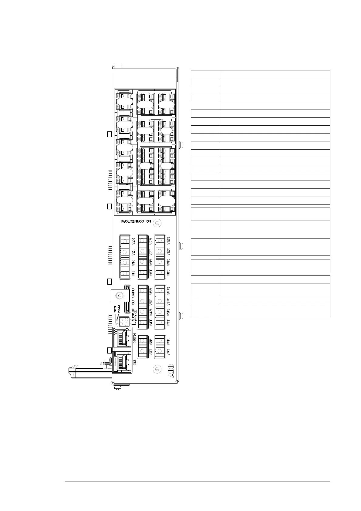
I/O terminals
Terminal Description
XAI Analog inputs
XAO Analog outputs
XDI Digital inputs
XDIO Digital input/outputs
XD2D Not in use
XD24 +24 V output (for digital inputs)
XETH Ethernet port
XPOW External power input
XRO1 Relay output RO1
XRO2 Relay output RO2
XRO3 Relay output RO3
XSTO Not in use
XSTO OUT Not in use
X12 Not in use
X13 Control panel connection
X485 Not in use
V1T/V1R,
V2T/V2R
Fiber optic connection to inverter modules 1 and
2 (VxT = transmitter, VxR = receiver)
V3T/V3R
…
V7T/V7R
Fiber optic connection to inverter modules 3…7
(BCU-12/22 only)
(VxT = transmitter, VxR = receiver)
V8T/V8R
…
V12T/V12R
Fiber optic connection to inverter modules 8…12
(BCU-22 only)
(VxT = transmitter, VxR = receiver)
SD CARD Data logger memory card for inverter module
communication
BATT OK Not in use
FAULT The control program has generated a fault. Refer
to the firmware manual of the inverter unit.
PWR OK Internal voltage supply is OK
WRITE Writing to memory card in progress.
Do not remove the memory card.
XDI
XSTO
X485
XD2D
XRO1
XRO2
XRO3
XDIO
XD24
XSTO
OUT
XAI
XAO
XPOW
 Loading...


