Instruction manual 504/05 | VM1 Vacuum circuit-breaker 37
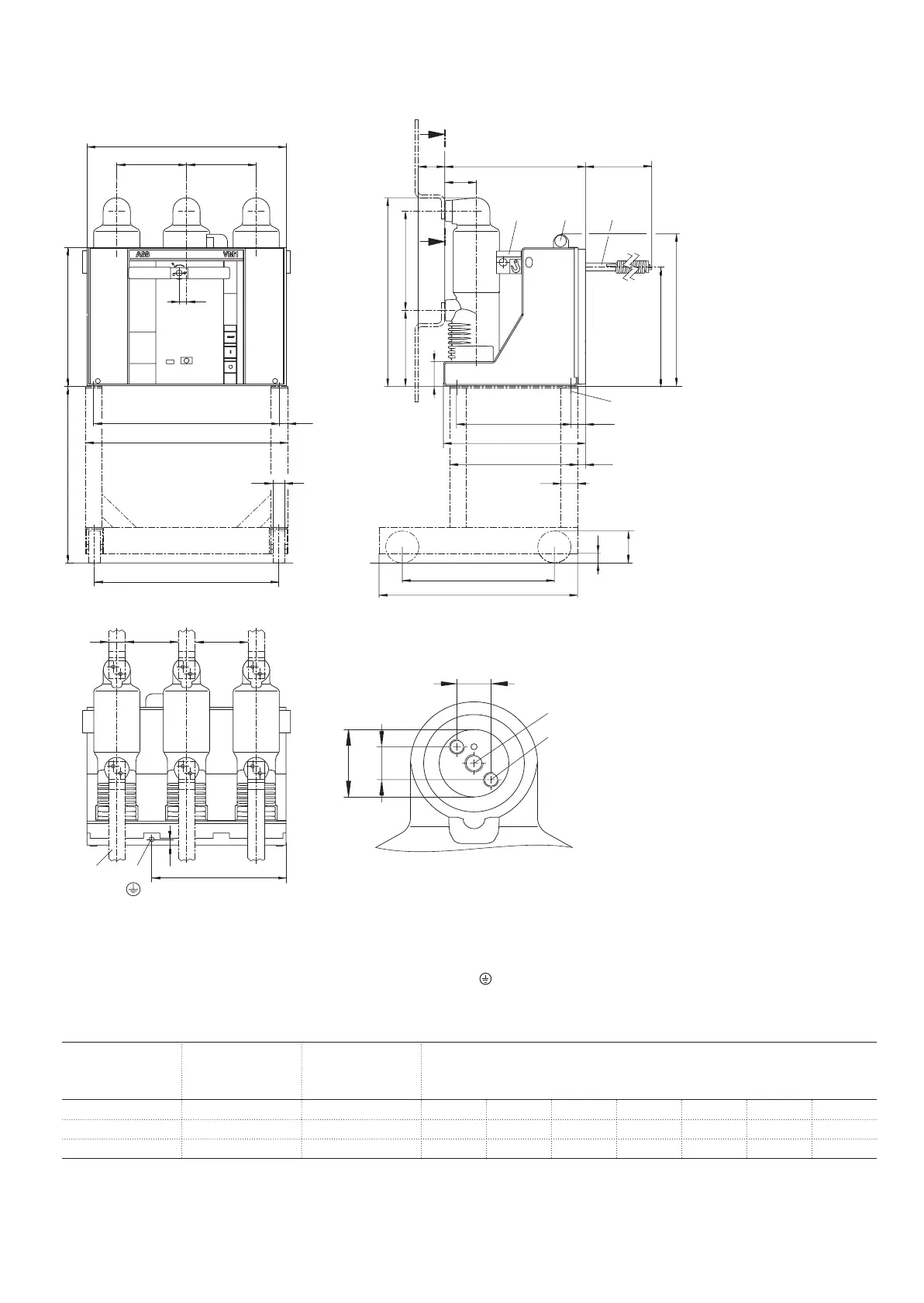
10.2.2 Dimensions
Circuit-breaker for fixed installation
ø45
22
22
A1: M12/18 deep
A2: M10/15 deep
+2
+2
A
530
670
a1
a
c
434
d
p p
25
35
22
550
400
424
95
M
428
e
385
50
24
44
M12
30
100
588.5
310237.5
77.5
355.5
475
A
50 M M
M12A3
f
24
GA
K
T
A - A
H
H = Emergency manual opening lever
K = Cable entry
T = Handling bores, both sides
Note: Remove the lifting lugs on both sides before commissioning)
A = View „A“
M = Minimum distance to DIN VDE 0101
GA = Tested terminal zone
Figure 10/1: Dimensional drawing of circuit-breaker type VM1
1)
- 12 / 17.5 kV, 1250 / 1600 A, 40 kA
A1 = Terminal for contact arm
A2 = Terminal for connecting bar
A3 = Terminal bar to DIN 46 433
= Earthing conductor terminal, use contact washer
Rated
voltage
Rated
current
Rated
short-circuit-
breaking current
kV A kA p a a
1
c d f e
12 / 17.5 1250 / 1600 40 210 610 555 560 600 405 320
12 / 17.5 1600 40 275 750 695 700 750 545 345
1)
See table page 35 and 36 (column Dimensional drawings)
BA 504-05 GB_29102012.indd 37 30.10.12 13:45
 Loading...