40 VM1 Vacuum circuit-breaker | Instruction manual 504/05
10.3 Technical data
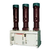
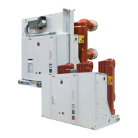
Circuit-breakers on withdrawable part
1)
10.3.1 Performance data and weights
Rated voltage kV 12 17.5 24
Rated frequency Hz 50/60 50/60 50/60
Rated lightning impulse withstand voltage kV 75 95 125
Rated power frequency withstand voltage kV 28 38 50
Rated of rise of transient recovery voltage kV/µs 0.34 0.42 0.47
Peak transient recovery voltage kV 20.6 30 41
Rated operating sequence O-3 min-CO-3 min-CO
Rated operating sequence for autoreclosing O-0.3 s-CO-3 min-CO
Guideline values for function times:
Closing time ca. 45…60 ms
Opening time ca. 35…50 ms
Arcing time (at 50 Hz) ≤ 15 ms
Break time ≤ 60 ms
Minimum command time on closing 20 ms
Minimum command time on opening 20 ms
1)
For further details on the cell type assignments see the section on dimensions for circuit-breaker on withdrawable assembly
2)
At operating voltages lower than the rated voltage, the same values fundamentally apply as for the rated voltage. Higher values on request.
3)
With a motorized withdrawable part, the weight is increased by approx. 2 kg.
4)
Breakers for 4000 A with fan cooling
5)
Use in ZS8.4 only
Breaker
type
Rated
voltage
Rated
current
Rated
short-
circuit-
breaking
current
symm.
2)
Short-
circuit
breaking
currentr
asymm.
2)
Rated
short-
circuit
making
current
(peak)
2)
Rated
short-
circuit
duration
Pole
centres
1)
Weight
1) 3)
Permissible
number
of vacuum
interrupter
switching
operations
Dimen-
sional
drawings
VM1.. kV A kA kA kA s mm approx.
kg
Figure
10a/10b
Page 33/34
Figure-no.
1206-16
5)
12 630 16 17.4 40 3 150 127 Diagram A 10/8
1212-16
5)
1250 150 131 Diagram A 10/8
1206-20
5)
630 20 21.8 50 3 150 127 Diagram B 10/8
1212-20
5)
1250 150 131 Diagram B 10/8
1206-25
5)
630 25 27.3 63 3 150 127 Diagram C 10/8
1212-25
5)
1250 150 131 Diagram C 10/8
1231-25 3150 275 280 Diagram C 10/5
1240-25
4)
4000
4)
275 280 Diagram C 10/5
1231-31 3150 31.5 34.3 80 3 275 280 Diagram D 10/5
1240-31
4)
4000
4)
275 280 Diagram D 10/5
1212-40 1250 40 43.6 100 3 210 215 Diagram E 10/4
1216-40 1600 210/275 215/220 Diagram E 10/4
1220-40 2000 275 220 Diagram E 10/5
1225-40 2500 275 225 Diagram E 10/5
1231 40 3150 275 280 Diagram E 10/5
1240-40
4)
4000
4)
275 280 Diagram E 10/5
1212-50 1250 50 54.5 125 3 210 222 Diagram F 10/7
1216-50 1600 210/275 222/230 Diagram F 10/7
1220-50 2000 275 260 Diagram F 10/6
1225-50 2500 275 265 Diagram F 10/6
1231-50 3150 275 290 Diagram F 10/6
1240-50
4)
4000
4)
275 290 Diagram F 10/6
BA 504-05 GB_29102012.indd 40 30.10.12 13:45
 Loading...