1.3.5 Controller Requirements
1.3.5.1 General Requirements
The monitor shall include a controller capable of
converting the analog RGB signal from a standard
1280x800 resolution video controller in the CPU to
a signal which can be displayed on the panel. The
controller will include a PLL, A/D converters, LVDS
transmitter and other circuitry necessary to perform
its function. The PLL shall be stable enough to
ensure that a static image from the CPU is placed
in the same physical location on the flat panel in
each frame.
1.3.5.2 Video Stretching
The monitor shall contain provisions to “stretch” the
video signal, so that an input signal from the
computer in any resolution smaller than 1280 x
1024 is automatically expanded to fill the entire
screen.
1.3.5.3 Panel Timing and Interface
The controller supplied with the monitor shall
control all panel timing. This controller shall
adequately insulate the monitor from the computer,
so that no possible combination of input signals
from the computer shall cause damage to the flat
panel or any other component of the monitor. The
LCD panel interface shall support the TFT
standard.
1.3.6 DC - AC Inverter Requirements
The DC-AC inverter is on the power board. The
frequencies used by the DC-AC inverter used to power the
backlight shall be chosen so as to prevent any noticeable
effects on the flat panel (such as a rolling effect).
1.3.7 Power Supply Requirements
The AC to DC converter power supply for the monitor shall
be an external AC to DC converter ”brick” This brick shall
have an IEC receptacle for main power input and a pin - in
---socket for DC power out. The brick shall provide
sufficient power for both the monitor and the backlight
assembly, and shall meet requirements specified in Table
2.
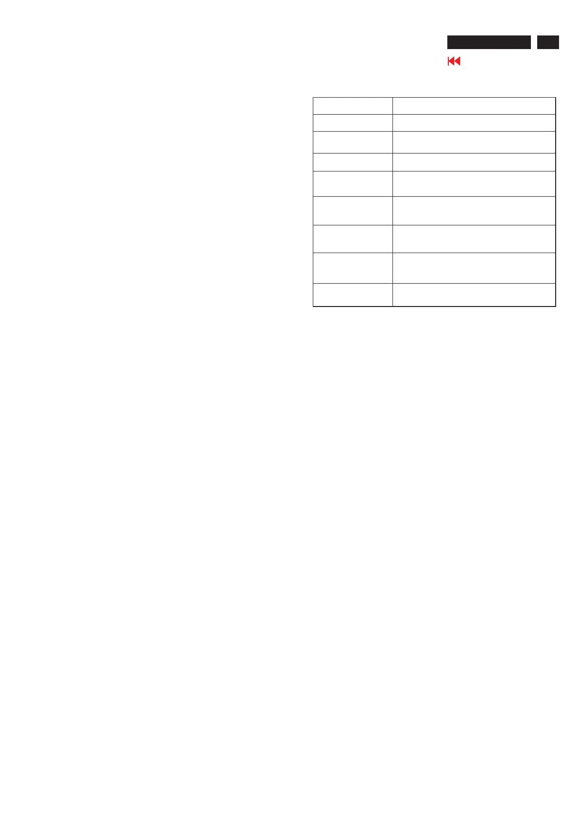
1. Product Specification (continued)
Input V oltage Range
The operating range shall be from 90 to 132 and 195 to 265 A VC
sinusoidal for all m odels specified.
Input Frequency Range
Input power frequency range sha;; be from 47.5 to 63 Hz over the
specified input voltage range.
Power C onsumption
Power consumption for the m onitor shall be less than 46W over the
specified vo ltage and frequ ency ranges. In suspend or sleep m o de
the po w er con su m p tion w ill be less than 2W .
Line Fuse
The A C input shall be fused and become electrically open as a result
on an unsafe current level. The fuse m any not be user replaceable.
Initial Cold Sta rt
The pow er supply shall start and function properly when under full
load, w ith worst case conditions of input voltage, input frequenct,
operating temperature, and cold backlight lamps.
In rush C ur r ent
The inrush current m ust be limited to 30A when operated at
120VA C, and 50A when operated at 220V AC. Inrush current is
m easured at an am b ient tem perature of 25
o
C , wi th the un it
tem p era ture stab ilize d in th e po w er-o ff.
Hot Start Cycle
The pow er supply shall be damaged w hen switched O N for one
second and OFF for one second for seven consecutive after
operating for one hour at full load, 25
o
C , a nd no m in al inp ut line
voltage.
Under Voltage
Th e power s up ply shall conta in protec tion circu itry su ch that the
app lica tion of an inpu t volta ge belo w th e m inimum specifie d in this
table shall not cause damage to the power supply unit nor cause
failure of the input.
Line Transient
The pow er supply shall operate within IEC 801-4 (± 1KV) and IEC
801-5 (± 2KV ) for the dom estic U .S. version. The U PS pow er
supply shall operate and com ply w ith CE m ark.
AC to DC Converter Requirements
Table 2
1.3.8 Display Communications Channel
The monitor assembly shall provide a display
communications channel that conforms to VESA
DDC2Bi hardware requirements. This configuration
shall contain the 128-byte EDID file as specified by
VESA EDID standard.The monitor should not write to
the EDID file for the first two minutes of operation
following power-up UNLESS some action taken by the
user or the host CPU forces the write (for instance,
requesting the serial number via the OSD).
Furthermore, it is recommended that CMOS switches
be incorporated to isolate the DDC IC from outside
connections while the EDID Fault Management is
being updated. This is to prevent corruption of the data
by attempts to read the data while it is being changed.
1.3.9 Firmware Update Function (same ISP function)
The update firmware need through from the D-Sub
connector, use DDC I2C bus to do update firmware.
1.4 PANEL ELECTRICAL
1.4.1 General Requirements
The panel used as the display device shall be an
1280x800 resolution, 15.0” diagonal TFT-LCD. This
panel shall be approved for use in this monitor.
1.4.2 Panel Timings
The controller included with the monitor shall translate
all video timings from the CPU that meet the timing
requirements listed in Panel specification into timings
appropriate for the panel. Under no circumstances may
the controller supply the panel with timings that may
result in damage. The controller shall insulate the
panel from the CPU , so that the panel shall always be
driven per it's own specification regardless of the
timings being sent from the CPU.
Go to cover page
5
ACER AL1516W

 Loading...