Jumper and Connector Locations 5-3
Jumper and Connector Locations
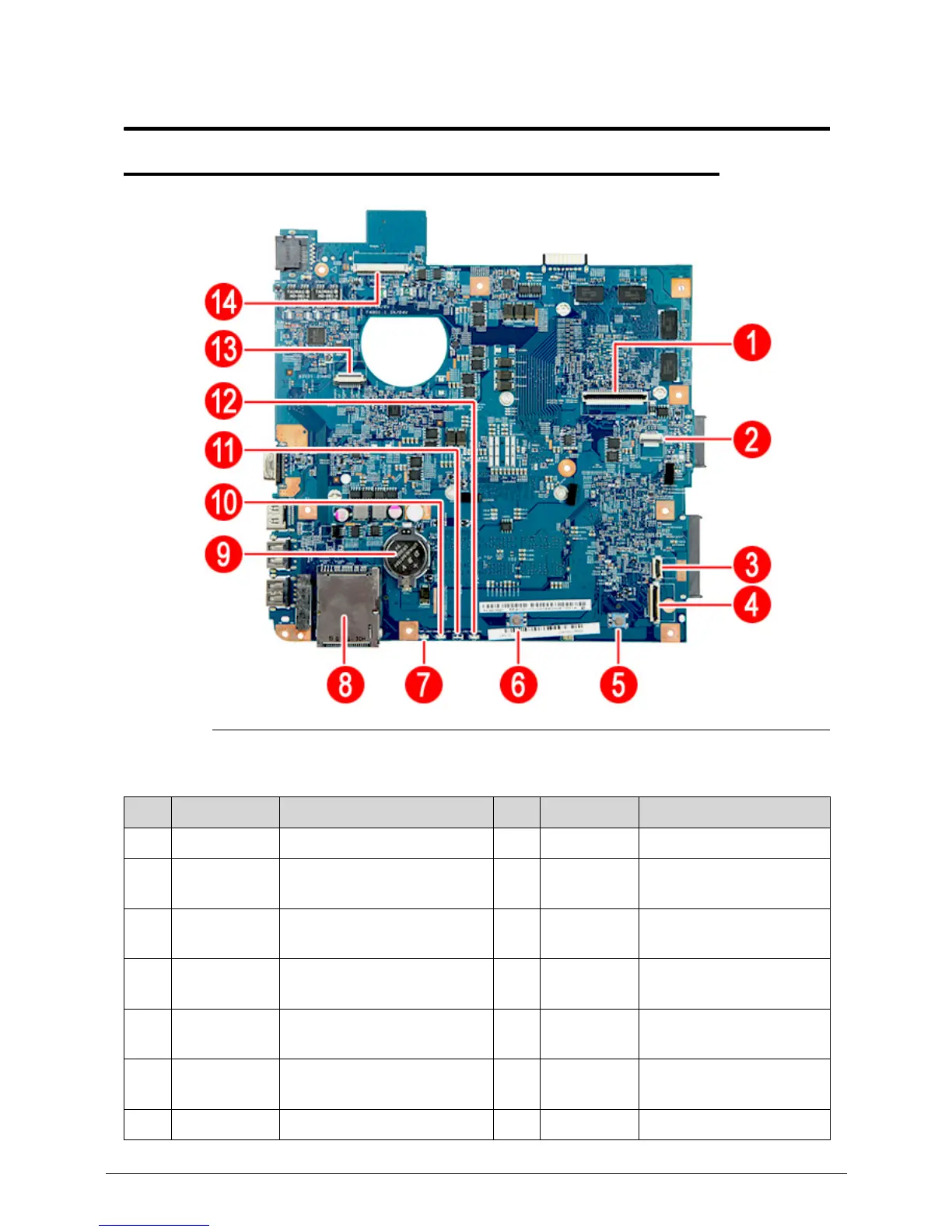
Mainboard Layout 0
Figure 5-1. Mainboard Top
Table 5-1. Mainboard Top
No. Code Component No. Code Component
1 KB1 Keyboard cable connector 8 CARD1 Memory card reader
2 TPAD1 Touchpad board cable
connector
9RTC1 Battery
3 USBCN2 USB board cable
connector
10 CHARGE
R_LED1
Battery charge indicator
4 USBCN1 USB board cable
connector
11 MEDIA_
LED1
Hard drive activity
indicator
5 SW_R1 Touchpad button 12 COM_
LED1
Bluetooth/Wireless
network indicator
6 SW_L1 Touchpad button 13 PWRCN1 Power button board
cable connector
7 PWR_LED1 Power indicator 14 LCD1 LCD cable connector
 Loading...