Machine Maintenance 3-7
Disassembly Process 0
The disassembly process is divided into the following stages:
External Module Disassembly
Main Unit Disassembly
LCD Module Disassembly
The flowcharts provided in the succeeding disassembly sections illustrate the entire
disassembly sequence. Observe the order of the sequence to avoid damage to any of the
hardware components. For example, if you want to remove the main board, you must first
remove the keyboard, then disassemble the inside assembly frame in that order.
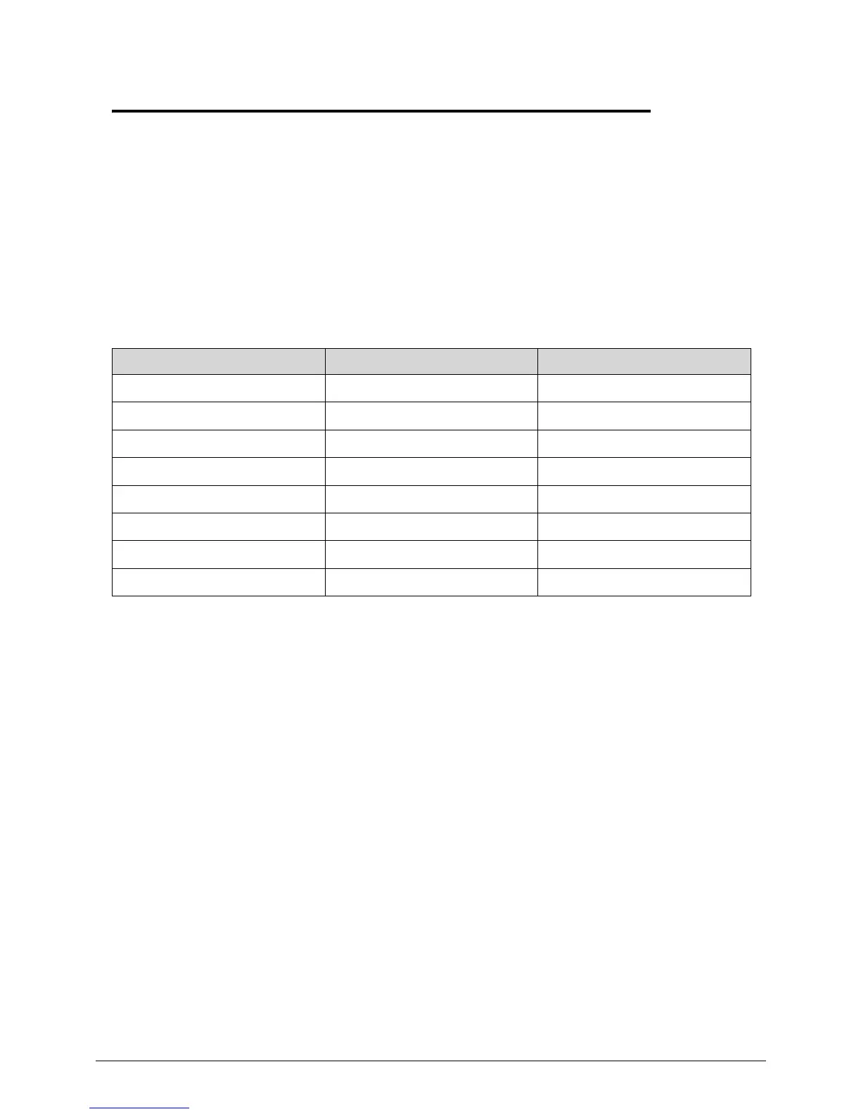
Table 3-1. Main Screw List
Screw Quantity Acer Part Number
M2 x L3 4 86.E1562.2R0
M2 x L3 (black) 12 86.00F80.723
M2.5 x L4 4 86.00H36.534
M2.5 x L5 2 86.00F87.735
M2.5 x L6 21 86.00E12.536
M3 x L4 2 86.9A524.4R0
Special Screw 1 86.9A563.3R0
Thermal Screw 6 N/A
 Loading...