Jumper and Connector Locations 5-3
Jumper and Connector Locations
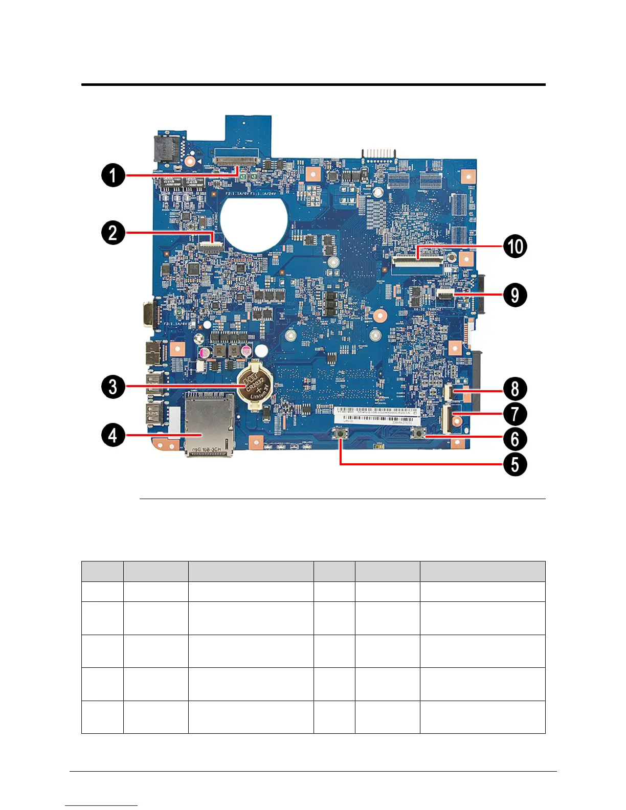
Figure 5-1. Mainboard Top
Table 5-1. Mainboard Top
No. Code Component No. Code Component
1 LCD1 LCD cable connector 6 SW_R1 Right touchpad button
2 PWRCN1 Power button board
cable connector
7 USBCN1 USB board cable
connector
3 RTC1 Battery 8 USBCN2 USB board cable
connector
4 CARD1 Memory card reader 9 TPAD1 Touchpad board cable
connector
5 SW_L1 Left touchpad button 10 KB1 Keyboard cable
connector
 Loading...