Chapter 3 Disassembly/Assembly Procedures and Parts List 33
a revised test and assembly procedure. The ERC should be checked against
schematics, component locator diagrams, and parts lists to ensure
compatibility. ERCs with values lower than those noted on the schematics,
component locator diagrams, and parts lists are described in a backdating
section. ERCs with a value higher that those noted will be covered by a
manual change sheet, manual update, or manual revisions.
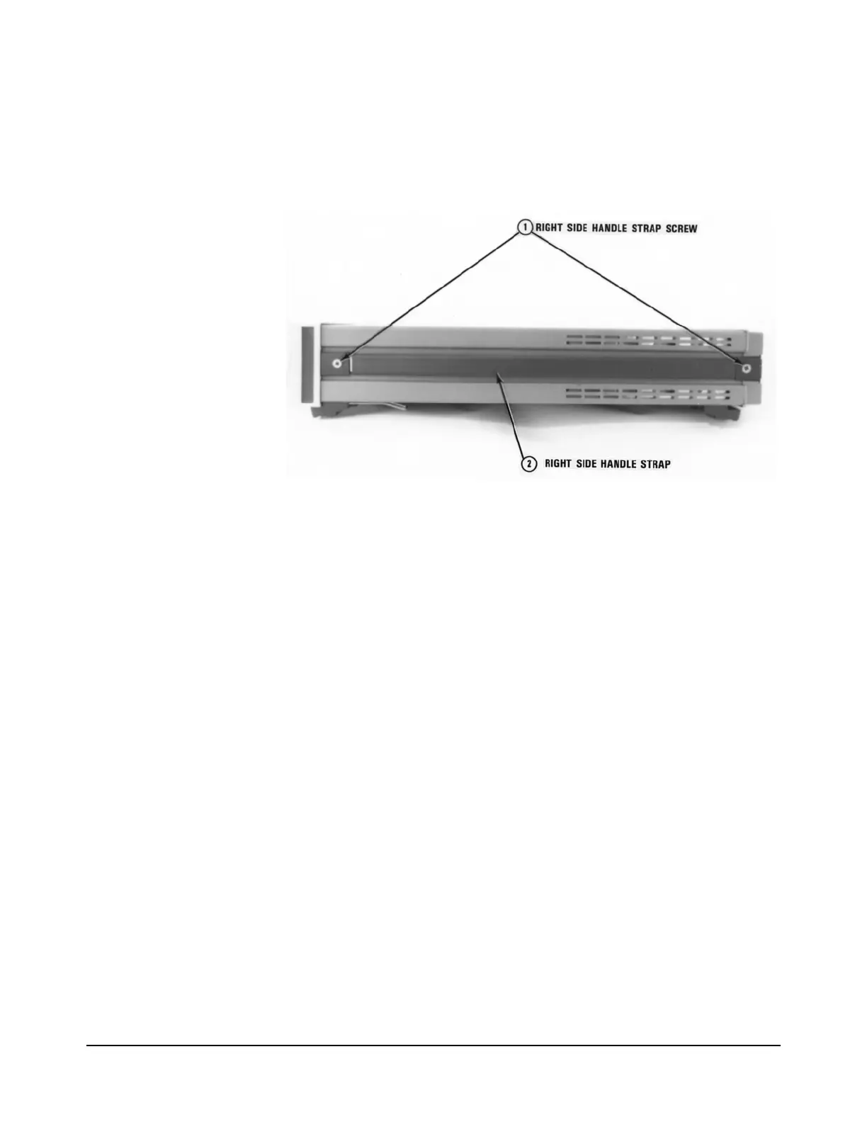
Figure 6. Right Side Handle Removal/Installation
Covers Removal/Installation Procedures
The following procedures show how to remove the top/bottom covers and
shields on the 3458A. Removal of the covers and shields are required to
replace the printed circuit board assemblies.
Tools Required You need:
1. #1 Pozidriv screwdriver
2. #TX15 Torx driver
3. #TX10 Torx driver
Covers Removal
Procedure
Do the following:
1. Remove all connections to the 3458A.
2. Remove ac power from the 3458A.
3. Refer to Figure 6. Turn the instrument so its right side (as seen from
the front) faces you.
4. Use the #1 Pozidriv to remove the right side handle strap screws.
Then remove the strap.
NOTE
The label numbers
in Figures 5 to 10
show the order of
cover removal. Use
reverse order for
installation.

 Loading...


