56 Chapter 3 Disassembly/Assembly Procedures and Parts List
Display Logic
Assembly
Removal/Installation
Procedures
The following procedures show how to remove and install the Display Logic
Board Assembly.
Removal Procedure 1. Use the Covers Removal Procedure in this section of the manual to
remove the 3458A top/bottom covers and top/bottom shields.
2. Set the 3458A on your workbench with the bottom facing you.
3. Refer to Figure 21. Do the following:
a. Locate and pull the power switch pushrod off the power switch.
You may need to pry the pushrod loose with a small screwdriver.
Then remove the pushrod by pulling it out of the front panel from
the rear.
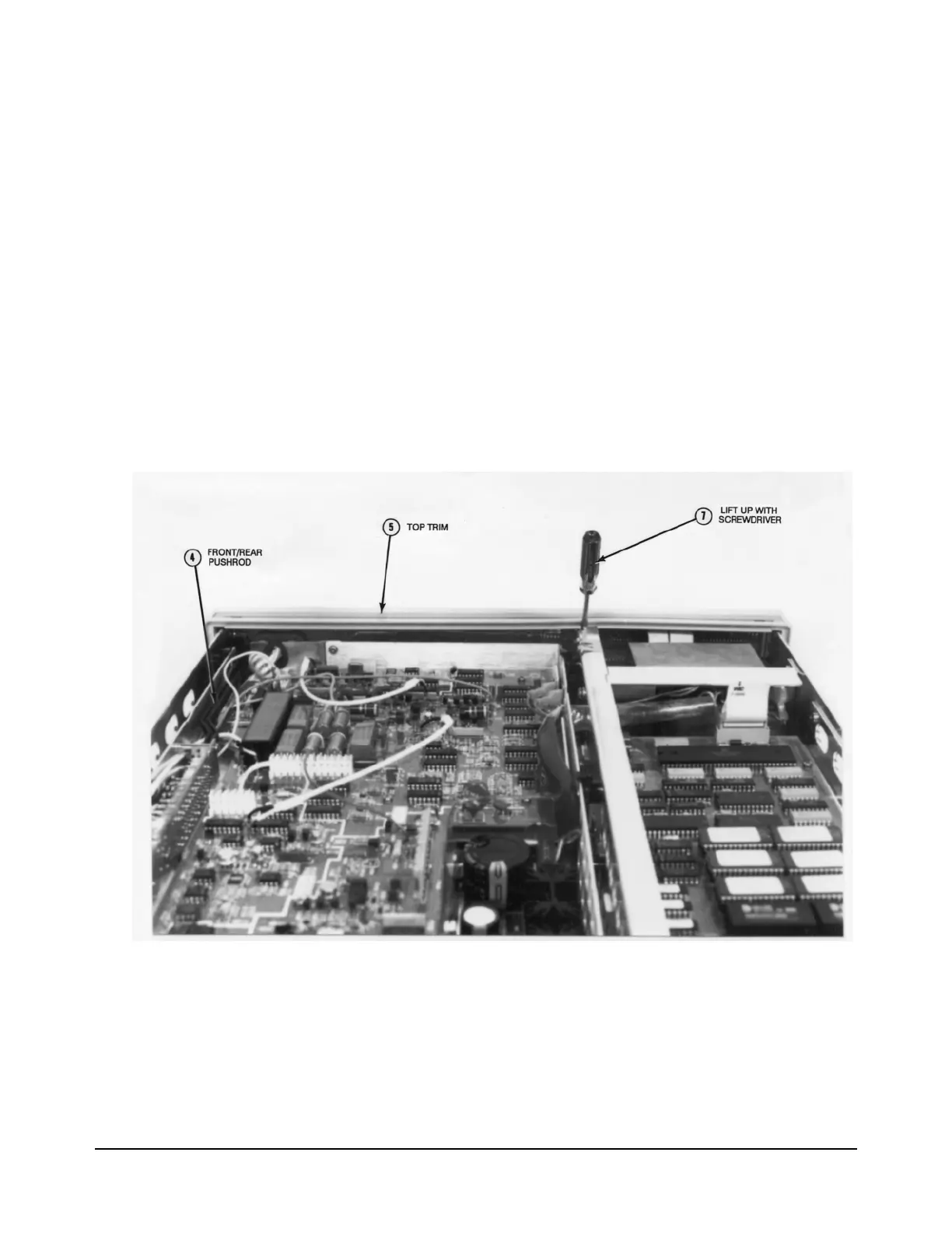
Figure 22. Top Trim and Front/rear Pushrod Locations, and Unlock Panel
b. Locate the grey 26-pin cable that connects the Outguard Power
Supply assembly to the Display assembly. Unplug this cable at the
Outguard Power Supply assembly.
c. Locate and pull the Guard switch pushrod off the Guard switch.
You may need to pry the pushrod loose with a small screwdriver.

 Loading...


