Chapter 3 Disassembly/Assembly Procedures and Parts List 49
Inguard Power
Supply Assembly
Removal/Installation
Procedures
The following procedures show how to remove and install the Inguard Power
Supply Printed Circuit Board Assembly.
Removal Procedure 1. Use the Covers Removal Procedure in this section of the manual to
remove the 3458A top/bottom covers and top/bottom shields.
2. Set the 3458A on your workbench with the top facing you.
3. Refer to Figure 17. Unplug the 5-wire cable from the Inguard Power
Supply assembly. This cable is connected to the power transformer.
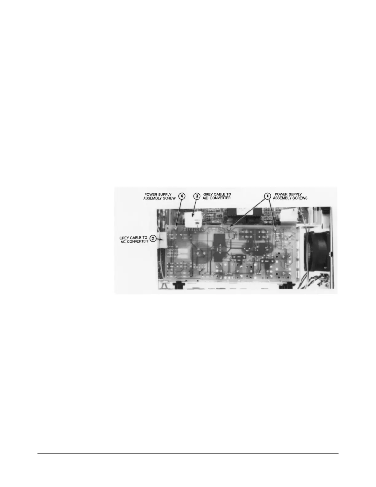
4. Refer to Figure 18 for the rest of this procedure.
5. Set the 3458A on your workbench with the bottom facing you.
Figure 18. Inguard Power Supply Assembly Removal/Installation
6. Locate the grey 20-pin cable that connects between the A/C Converter
assembly and Inguard Power Supply assembly. Unplug the cable at
the power supply assembly.
7. Locate the grey 20-pin cable that connects between the A/D Converter
assembly and Inguard Power Supply assembly. Unplug the cable at
the power supply assembly, and Inguard Logic assembly.
8. Use the #TX 10 Torx driver to remove the three screws on the Inguard
Power Supply assembly.
9. Push the Inguard Power Supply assembly toward the left, of the
instrument (as seen from the front) until it clears the slot in the chassis.
Then remove the board from the instrument.

 Loading...


