34980A Getting Started Guide 5
Removing a Slot Cover
Your 34980A is shipped from the factory with one slot uncovered and the remaining seven slots covered.
When performing tasks in this guide to become familiar with the instrument, you will install a plug-in
module into Slot 1. When you are ready to install additional modules, follow the procedure below to
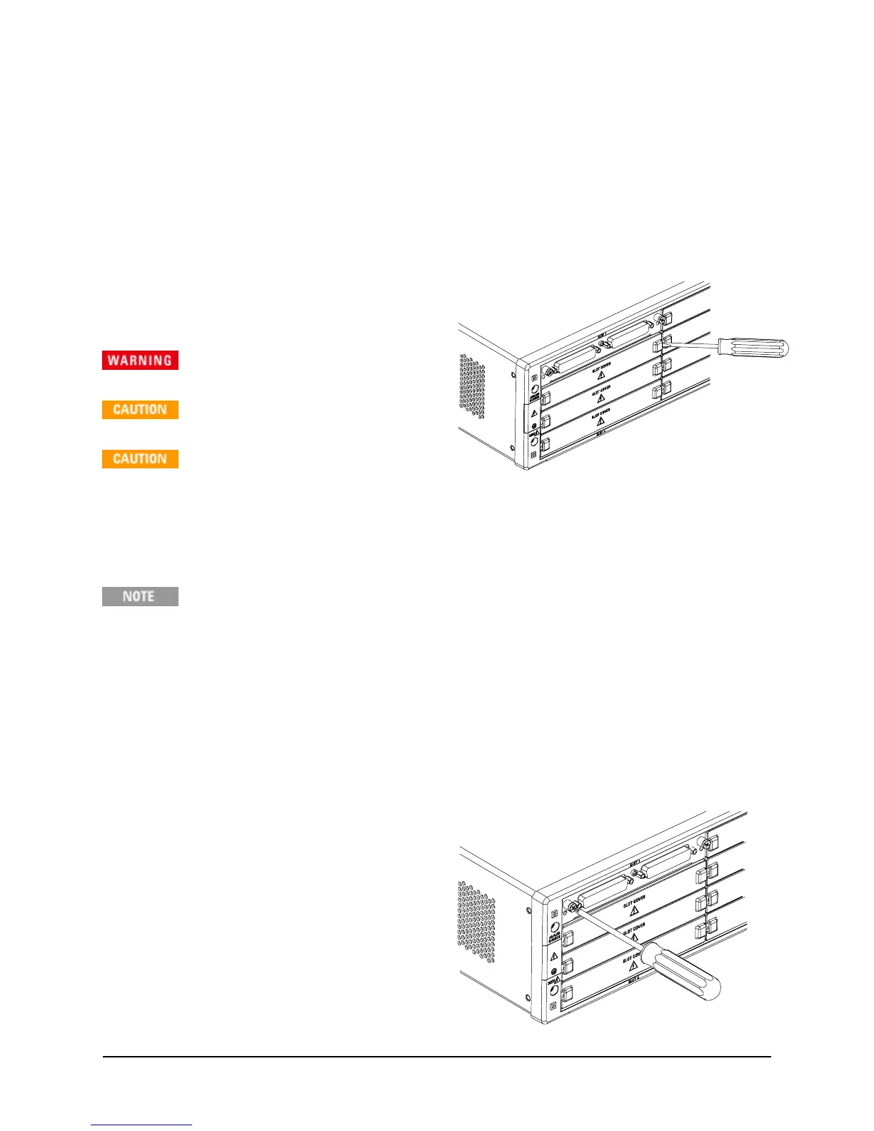
remove a slot cover.
Using a flatblade screwdriver, pry each side of the
slot cover until the cover releases from the slot.
With the slot cover removed, you can now install
a module in this slot.
Hazardous voltages may be
exposed on analog bus connectors.
For proper module cooling,
all unused slots must be covered.
Do not block air intake or exhaust
vents at the sides of the instrument.
Installing a Module
The
Safety Interlock
feature prevents connections to the Analog Buses if no terminal block
or properly-wired cable is connected to a module (available on the multiplexer and matrix
modules only). If the proper connections are not present, the Analog Bus relays will be
disabled on that module and the front panel “Safety Interlock” display annunciator will
turn on. See the 34980A
User’s Guide
for additional information.
Installing a Module for Use with Cables
If you are planning to use cables for your external connections, follow the procedure below to install
a plug-in module. If you are planning to use an optional terminal block to connect your external wiring,
see the procedure on page 6.
1. Install the module into a mainframe slot until
it fully seats with the backplane connector.
2. Using a Pozidriv #1 screwdriver, tighten the
two screws to secure the module in the
mainframe. Installation is now complete.
NEXT STEP:
Go to “Operating the Front Panel
Keyboard” on page 9.

 Loading...


