Page 15
English
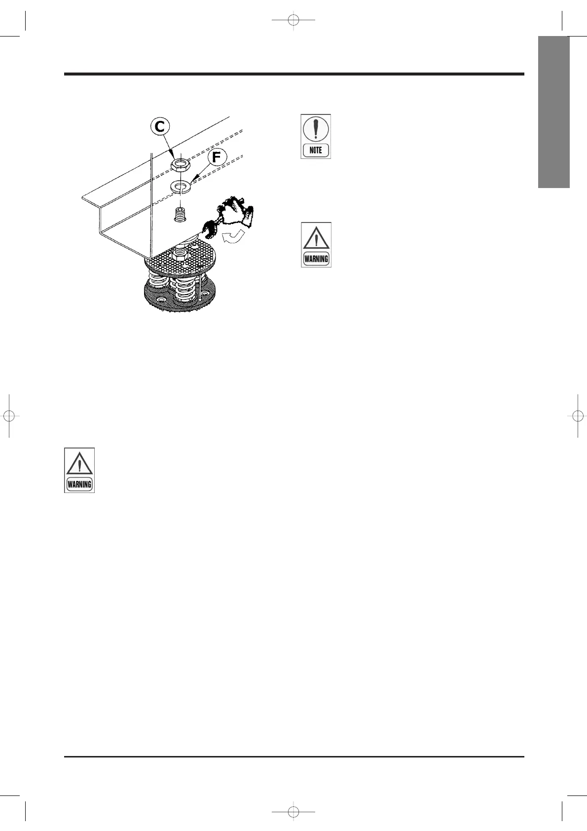
3) make sure that the base of the machine is resting
on the flat washer (E) of the jack. To offset any dif-
ference in height, work on high nut (D), using a
24 wrench. Clamp in the obtain position with the
grower washer (F) and the relevant low nut (C).
At the end of this operation, check that the machine
is elastic on its axes, and preset for the installation of
antivibrating joints in the water connections.
4.3 External hydraulic circuit
The external hydraulic circuit must ensure
the water flow to the evaporator under any
working conditions and with any adjust-
ment.
The external hydraulic circuit should consist of the fol-
lowing elements:
h
A circulation pump which delivers a sufficient wa-
ter flow and discharge head.
h
The capacity of the primary hydraulic circuit
should not be less than 5 litres/KW of cooling ca-
pacity, in order to prevent the repeated start-up of
the compressor and any damage to it. If the water
capacity in the primary piping of the circuit and in
the evaporator is lower than this value, an insulat-
ed storage tank shall be installed.
h
A membrane expansion vessel provided with safe-
ty valve with vent, that must be visible.
Installation
The capacity of the expansion vessel must
allow for an expansion of at least 2% of the
volume of the fluid in the circuit (evapora-
tor, piping, user circuit and standby tank, if
any). The expansion vessel needs not be
isolated, because no water can circulate in-
side it.
h
A flow meter, to disable the appliance when the
water is not circulating.
The flow meter must be connected in series,
as shown in the wiring diagram of the con-
trol panel.
To install the flow meter, conform to the manufactur-
er’s instructions.
As a general rule, the flow meter must be mounted
on a horizontal pipe, and its distance from the
curves must be 10 times the diameter of the pipe, far
from valves or other components that may hinder the
water flow upstream of or downstream from the flow
meter.
h
The air exhaust valves must be mounted in the
highest point of the piping.
h
The stop valves must be mounted on the water in-
let/outlet piping of the evaporator and the heat re-
covery condenser.
h
The drain points (provided with plugs, cocks etc.)
must be positioned in the lowest point of the pip-
ing.
Furthermore:
h
Provide the evaporator with a by-pass circuit
equipped with valve, to wash the plant.
h
Insulate the piping, to prevent the risk of heat loss.
h
Install a filter on the suction side of the evaporator
or the heat recovery condenser.
 Loading...