Page 74
Technical data
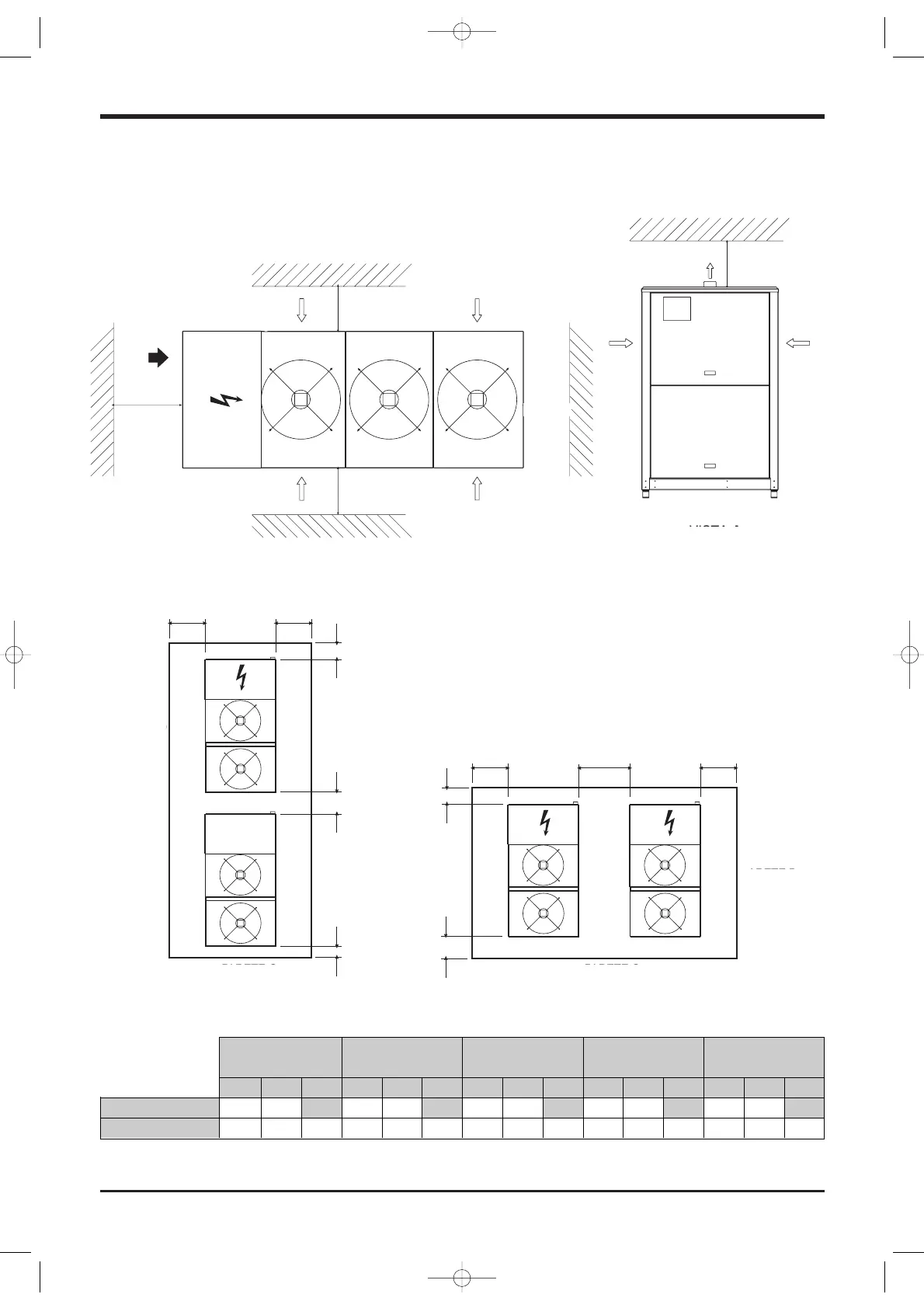
8.6 Service spaces
Installation of Single Units
A and C SCREENED A and B SOLID B and D SCREENED A and B SCREENED A and D SCREENED
B and D SOLID C and D SOLID A and C SOLID C and D SOLID B and D SOLID
A1 A2 A3 A1 A2 A3 A1 A2 A3 A1 A2 A3 A1 A2 A3
Arrangement 1 (m) 1.0 1.0 1.0 1.0 0.8 0.8 1.0 0.8 0.8 1.0
Arrangement 2 (m) 1.0 1.5 1.0 1.0 2.0 1.0 0.8 2.0 0.8 1.0 1.5 0.8 0.8 1.5 1.0
A wall only may be higher that the units.
The area between the walls must be kept free from any obstacle which may hinder the free air inflow towards the unit(s).
Installation of several Units
3000 mm
VIEW A
ARRANGEMENT 2
ARRANGEMENT 1
WALL C
WALL D WALL B
WALL A
WALL C
WALL D
WALL B
WALL A
 Loading...