1785-UM022B-EN-P - February 2002
1-14 Installing Your ControlNet PLC-5 Processor
If your remote I/O link:
Use this
resistor
rating:
The maximum number of
physical
devices
that you can connect
on the link is:
logical rack
numbers that you
can scan on the
link is:
Operates at 230.4K bit/s
82Ω 32 16
Operates at 57.6K or 115.2K bit/s, and no devices listed below are linked
Scanners 1771-SN; 1772-SD, -SD2;
1775-SR, -S4A, -S4B;
6008-SQH1, -SQH2
Adapters 1771-AS; 1771-ASB (Series A Only); 1771-DCM
Miscellaneous 1771-AF
Connects to any device listed below:
Scanners 1771-SN; 1772-SD, -SD2;
1775-SR, -S4A, -S4B;
6008-SQH1, -SQH2
Adapters 1771-AS; 1771-ASB (Series A Only); 1771-DCM
Miscellaneous 1771-AF
150Ω 16 16
Operates at 57.6K or 115.2K bit/s, and you do not require over 16 physical devices
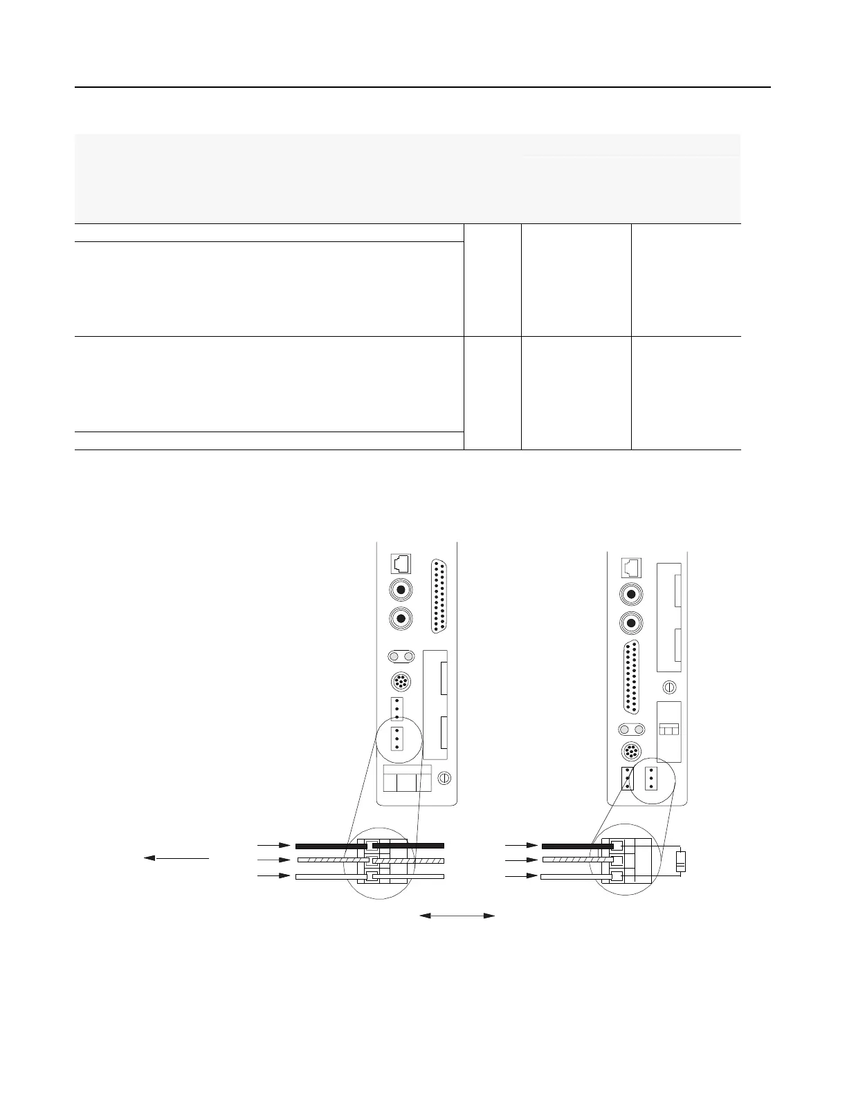
You can install a remote I/O link two ways:
- trunk cable/drop cable--from the drop cable to the connector screw terminals on the remote I/O connectors of the processor
- daisy chain--to the connector screw terminals on the remote I/O connectors of the processor and then to the remote I/O screw terminals of the next remote
I/O device
To connect remote I/O cable, use the Phoenix MTSB2.5/3-ST 3-pin header connector provided in the accessory kit.
1. Run the 1770-CD cable from the processor
to each remote I/O adapter module or processor
in the remote I/O system.
2. Connect the signal conductor with blue
insulation to the 3-pin connector terminal
labeled 1 on the processor and to each
remote I/O adapter module (or PLC-5
adapter) in the remote I/O system.
3. Connect the shield drain wire to the center
terminal of the 3-pin connector.
4. Connect the signal conductor with clear
insulation to the 3-pin connector terminal
labeled 2.
5. Tie-wrap the remote I/O network cable to
the chassis to relieve strain on the cable.
6. Terminate the remote I/O link by connecting
an external terminator resistor between the
remote I/O terminals labeled 1 and 2.
1770-CD
Blue
Shield
Clear
Shield
Clear
Blue
1770-CD
To another I/O
link device
PLC-5/40C, -5/46C,
-5/80C Processor
PLC-5/20C
Processor
82W or
150W
resistor
Terminate both ends of a remote I/O link

 Loading...


