EasyManuals Logo
Home>Allen-Bradley>Network Hardware>PicoTM Controller 1760

Allen-Bradley PicoTM Controller 1760 User Manual

Allen-Bradley PicoTM Controller 1760
66 pages
To Next Page IconTo Next Page
To Previous Page IconTo Previous Page
Page #22 background imageLoading...
Page #22 background image
Publication 1760-GR001C-EN-P - April 2005
1-14 Pico Controller
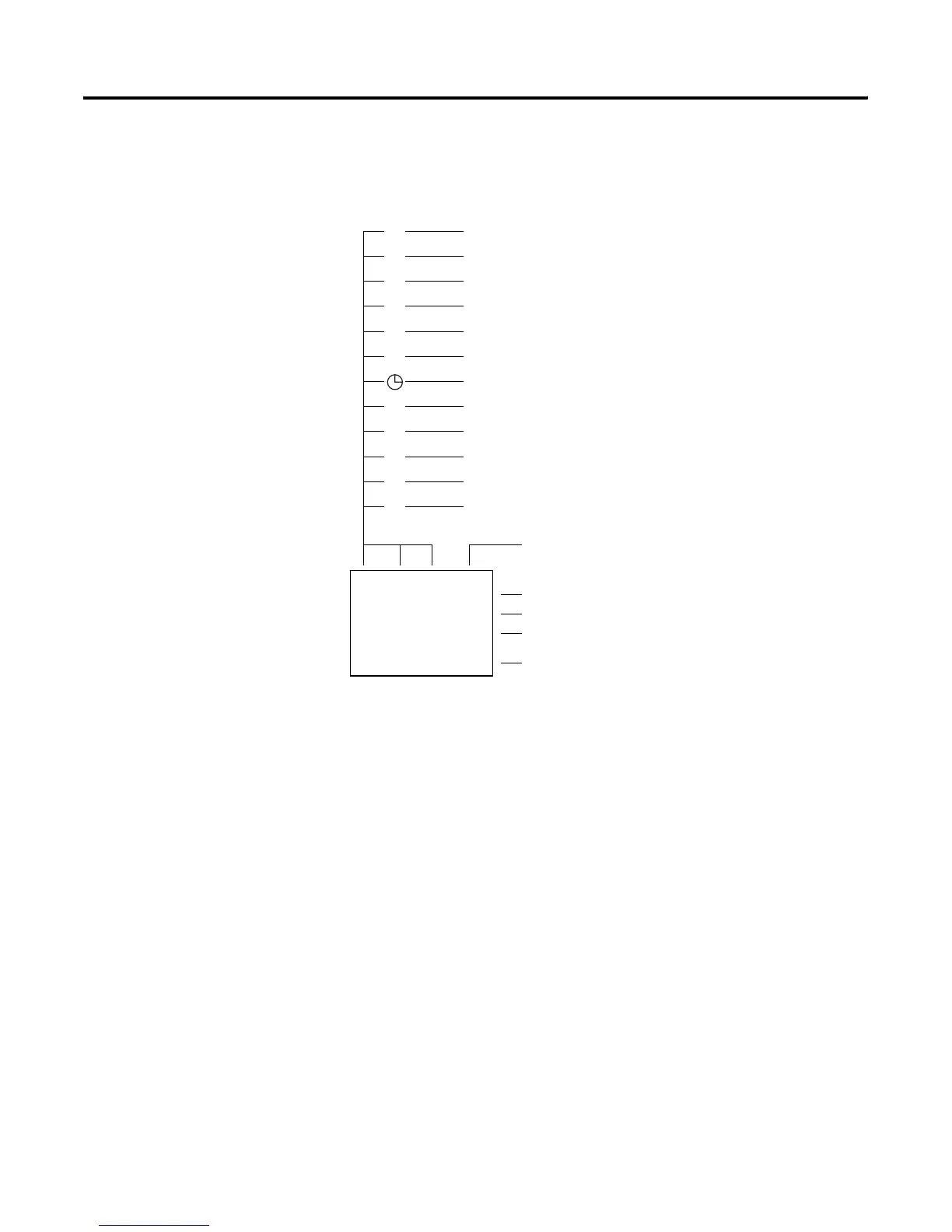
Circuit Diagram Symbols
P
I
Q
M
T
C
A
:
R
S
I1 -M2 -T1 -{Q1
I2 -Q1
D
I3-M2-T2----{Q2
Cursor button as input
Contact for input
Contact for output
Contact for internal marker bits
Contact for timer relay
Contact for counter relay
Contact for real time clock switch
Analog comparator contact
Contact for text display (1)
Contact for jump
(1)
Expansion Inputs
(1)
Contact for internal marker relay or
Expansion Output
(1)
Coil Field
1st circuit connection
2nd circuit connection
3rd circuit connection
41st circuit connection
Last circuit connection
(1) For 1760-L18xxx only

Questions and Answers:

Question and Answer IconNeed help?

Do you have a question about the Allen-Bradley PicoTM Controller 1760 and is the answer not in the manual?

Allen-Bradley PicoTM Controller 1760 Specifications

General IconGeneral
BrandAllen-Bradley
ModelPicoTM Controller 1760
CategoryNetwork Hardware
LanguageEnglish

Related product manuals