EasyManuals Logo
Home>Allen-Bradley>Network Hardware>PicoTM Controller 1760

Allen-Bradley PicoTM Controller 1760 User Manual

Allen-Bradley PicoTM Controller 1760
66 pages
To Next Page IconTo Next Page
To Previous Page IconTo Previous Page
Page #35 background imageLoading...
Page #35 background image
Publication 1760-GR001C-EN-P - April 2005
Drawing a Circuit with Pico 2-9
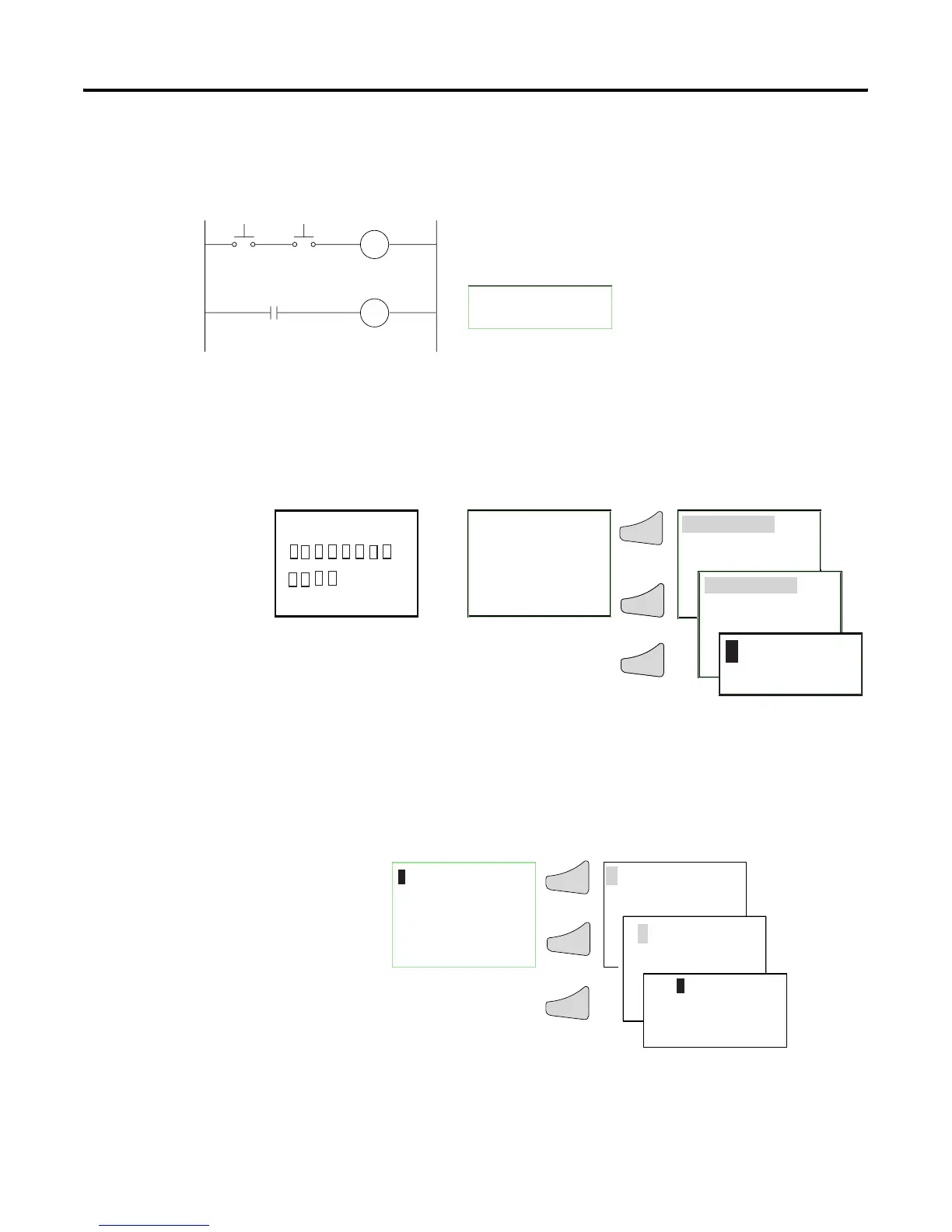
Example: Creating a Circuit
Diagram
Interconnect Contacts and Relays
Draw Circuit in Circuit Diagram Menu
Insert Contact “I1”
I1-I2----{Q1
S1 S2
CR1
M1
CR1
Connecting Pico
1. Connect S1 to Pico input terminal I1
2. Connect S2 to Pico input I2
3. Connect load M1 to Pico output Q1
Pico circuit diagram
I
12 3 4 5 6 7
8
MO
14:15
Q1234
STOP
1 ...5 ..8 ....
RE I P
MO 02:00 ST
.2 ..5 ..8 RUN
PROGRAM...
RUN
PROGRAM...
DELETE PROG
OkOk
Ok
OkOk
or
12-I/O Pico 18-I/O Pico
Start Status Display
I1
I1
I1
Ok
Ok
Ok
Circuit Diagram Display

Questions and Answers:

Question and Answer IconNeed help?

Do you have a question about the Allen-Bradley PicoTM Controller 1760 and is the answer not in the manual?

Allen-Bradley PicoTM Controller 1760 Specifications

General IconGeneral
BrandAllen-Bradley
ModelPicoTM Controller 1760
CategoryNetwork Hardware
LanguageEnglish

Related product manuals