EasyManuals Logo
Home>Allen-Bradley>Controller>PowerFlex 20-750-ENC-1

Allen-Bradley PowerFlex 20-750-ENC-1 User Manual

Allen-Bradley PowerFlex 20-750-ENC-1
302 pages
To Next Page IconTo Next Page
To Previous Page IconTo Previous Page
Page #156 background imageLoading...
Page #156 background image
156 Rockwell Automation Publication 750-IN001O-EN-P - October 2014
Chapter 4 Power Wiring
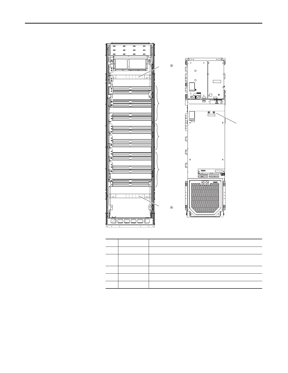
Floor Mount Frames 8…10
Bus Bar Locations
Figure 92 - Bus Bar Locations, AC Input Drives
No. Name Description
Power Bus R/L1, S/L2, T/L3 (Drive only.)
DC Bus DC+, DC- (The DC Bus is included with frame 9 and 10 drives. Frame 8 drives require
the field installed kit 20-750-BUS1A-F8.)
Power Bus U/T1, V/T2, W/T3 (Drive only or Cabinet Options Bay without power output options.)
PE Grounding Bar Terminating point to chassis ground for incoming AC line and motor shield.
DC+ and DC- Bus Voltage Test Points
R / L1
S / L2
T / L3
DC+
DC–
U / T1
V / T2
W / T3
PE
PE
Floor Mount Frame 8

Table of Contents

Questions and Answers:

Question and Answer IconNeed help?

Do you have a question about the Allen-Bradley PowerFlex 20-750-ENC-1 and is the answer not in the manual?

Allen-Bradley PowerFlex 20-750-ENC-1 Specifications

General IconGeneral
BrandAllen-Bradley
ModelPowerFlex 20-750-ENC-1
CategoryController
LanguageEnglish

Related product manuals