162 Rockwell Automation Publication 750-IN001O-EN-P - October 2014
Chapter 4 Power Wiring
Floor Mount Frames 8…10
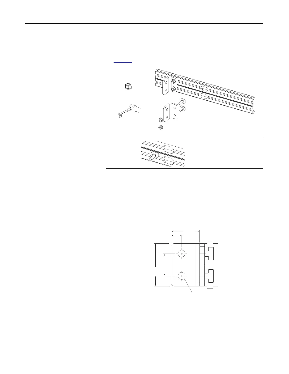
Power Terminal L-Brackets
Frame 8 drives and larger utilize movable L-bracket assemblies to connect AC
line input power, output to motor, and DC power to the extruded bus bars at the
back of the cabinet. Wiring must be connected to the L-brackets using customer-
supplied lugs (either crimp or mechanical type) and customer-supplied hardware.
See Figure 97
.
Additional Power Terminal L-Brackets
Frame 8 and larger drives come equipped with two L-brackets per AC phase. If an
application requires additional L-brackets, kit number 20-750-LBRKT1 is
available. Each kit contains three L-brackets and mounting hardware.
Figure 96 - L-Bracket Approximate Dimensions
Crimp terminals should be applied to cabling using the vendor-recommended
tooling. Mechanical terminals should be torqued per vendor instructions. When
using mechanical terminals, which may be large, be sure to maintain adequate
spacing to adjacent wires, terminals, and other parts.
Verify that clamp fits squarely in the bus bar
channel
M10 x 1.5
38.0 N•m (336 lb•in)
17 mm
52.7
(2.25)
85.1
(3.35)
ø 14.0
(0.55)
21.2
(0.83)
44.5
(1.75)
 Loading...


