32 Rockwell Automation Publication 750-IN001O-EN-P - October 2014
Chapter 2 Prepare for Installation
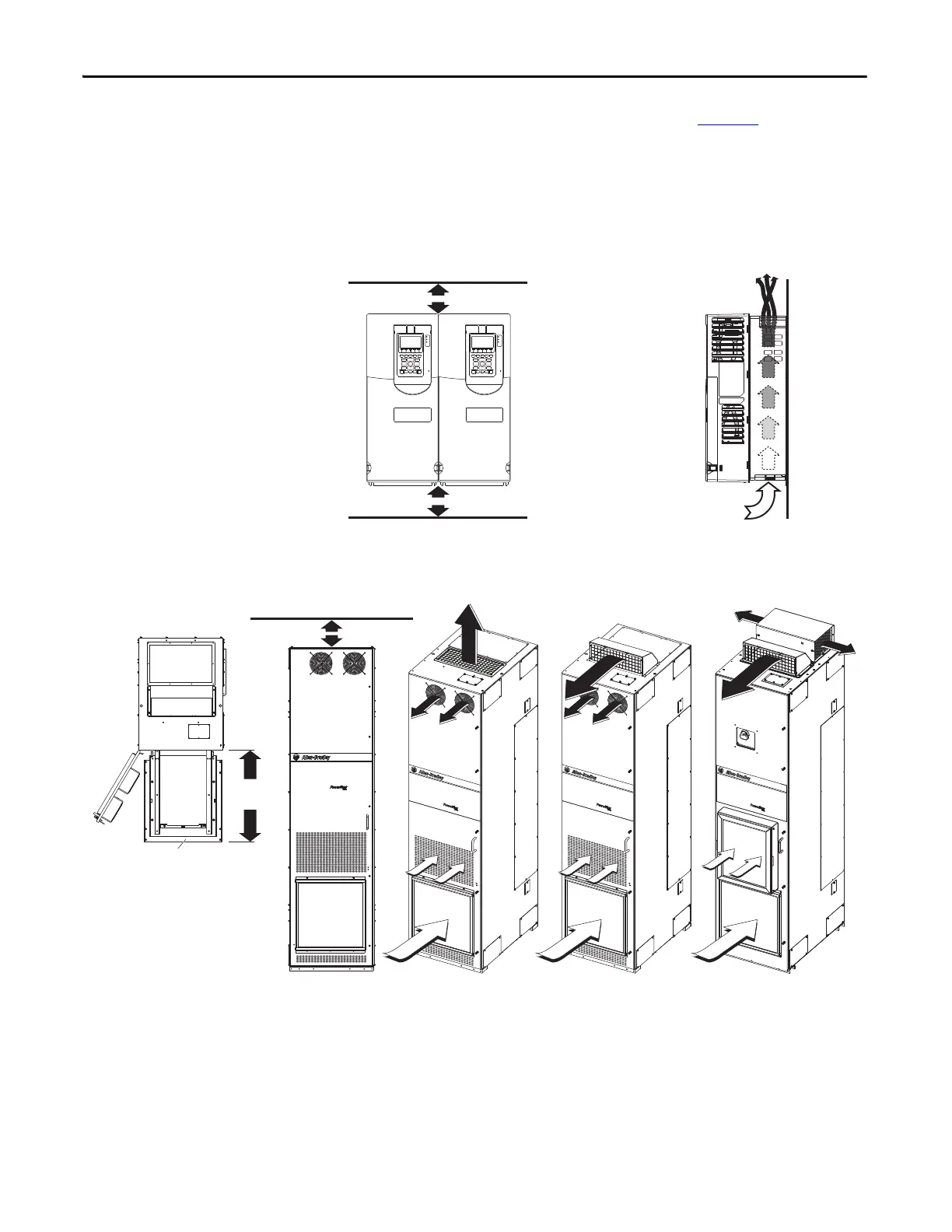
Minimum Clearances
Specified vertical clearance requirements (indicated in Figure 11) are intended to
be from the drive to the closest object that can restrict airflow through the drive
heat sink and chassis. The drive must be mounted in a vertical orientation as
shown and must make full contact with the mounting surface. Do not use
standoffs or spacers. In addition, inlet air temperature must not exceed the
product specification.
Figure 11 - Minimum Mounting Clearances – Wall Mount Frames 1…7
Figure 12 - Minimum Mounting Clearances – Floor Mount Drive Cabinets
76.2 mm (3.0 in.)
76.2 mm (3.0 in.)
Airflow through the drive
must not be impeded.
860 mm
(33.9 in.)
860 mm
(33.9 in.)
20-750-CART1-F8
182 mm (7.2 in.)
Airflow through the drive must not be impeded.
IP20, NEMA/UL Type 1
IP54, NEMA 12
IP20, NEMA/UL Type 1
with Optional Exhaust Hood
 Loading...


