296 Rockwell Automation Publication 750-IN001O-EN-P - October 2014
Chapter 5 I/O Wiring
Control Wiring - Frame 9 and
10 Drives with Cabinet
Options
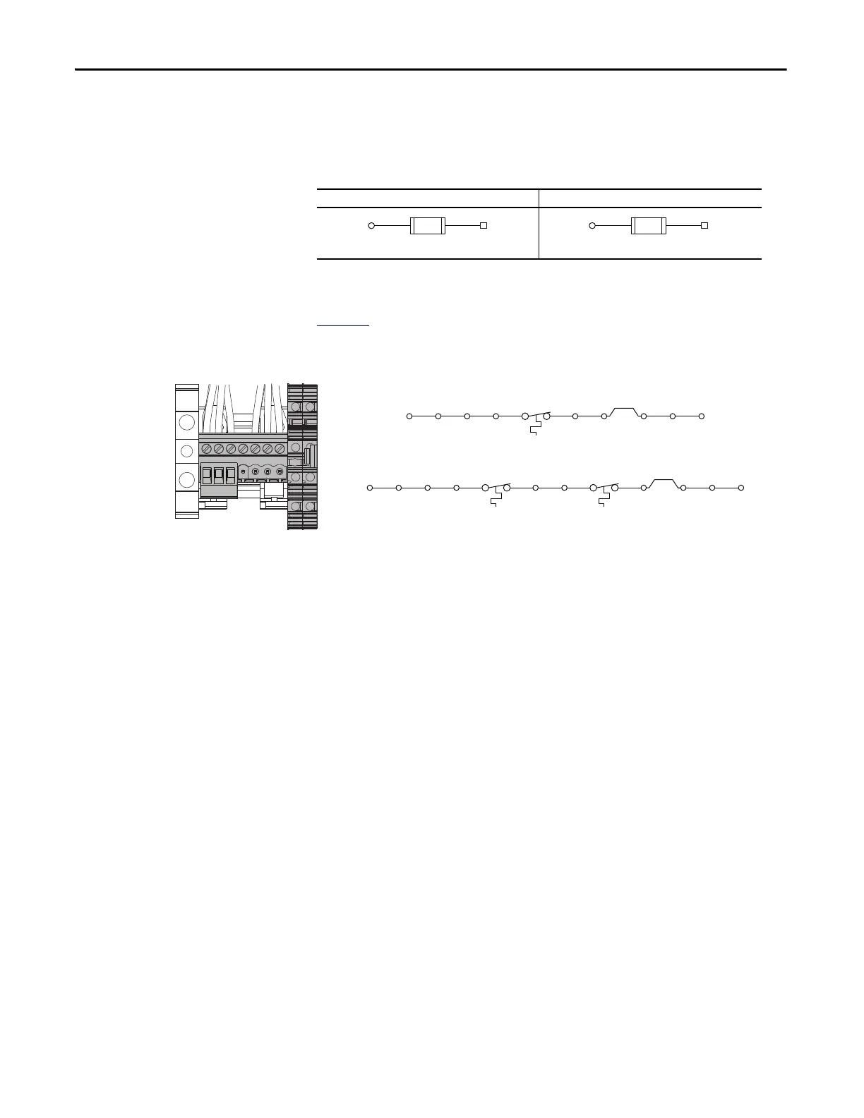
Frame 9 drives are shipped from the factory with control power set to 120V AC.
To change control voltage to 230V AC, move the jumper as shown.
Table 101 - Control Power for Customer Use Voltage Selection - Floor Mount Frames 9 and 10
Drives
Control terminal block TB4 is mounted on the power option module. TB1
referenced in the illustrations below resides on the main control board. See
page 229
.
Figure 160 - Control Terminal Blocks TB3 and TB4 - Floor Mount Frames 9 and 10 Drives
120V AC, 60Hz, 4.2A (Factory Setting) 230V AC, 50Hz, 2.2A
TB3(H)T1 (X2)
FU12
600V AC, 3A, Class CC
TB3(H)TB4(6)
FU12
600V AC, 6A, Class CC
Reactor Thermostat
Thermostat with Reactor - Frame 9 Only
TB4(2)TB6(2) TB6(3) TB4(4)TB6(4) TB4(1)TB4(3) TB6(1)
TB1(Di 0dc)
TB1(+24V)
TS1
Thermostat without Reactor - Frames 9 and 10
TB6(2) TB4(2) TB6(3) TB6(4) TB4(1)TB4(4) TB6(1)
TB1(Di 0dc)
TB1(+24V)
TS1
TB3
TB4
 Loading...


