Rockwell Automation Publication 520-UM001G-EN-E - September 2014 19
Installation/Wiring Chapter 1
AC Supply Source
Considerations
Ungrounded Distribution Systems
Disconnecting MOVs
To prevent drive damage, the MOVs connected to ground shall be disconnected
if the drive is installed on an ungrounded distribution system (IT mains) where
the line-to-ground voltages on any phase could exceed 125% of the nominal line-
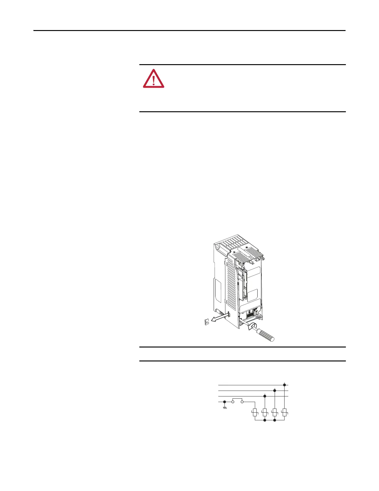
to-line voltage. To disconnect these devices, remove the jumper shown in the
diagrams below.
1. Turn the screw counterclockwise to loosen.
2. Pull the jumper completely out of the drive chassis.
3. Tighten the screw to keep it in place.
Jumper Location (Typical)
Phase to Ground MOV Removal
ATTENTION: PowerFlex 520-series drives contain protective MOVs that are
referenced to ground. These devices must be disconnected if the drive is
installed on an ungrounded or resistive grounded distribution system.
ATTENTION: Removing MOVs in drives with an embedded filter will also
disconnect the filter capacitor from earth ground.
Tighten screw after jumper removal.
R/L1
S/L2
T/L3
1234
Three-Phase
AC Input
Jumper

 Loading...


