Rockwell Automation Publication 520-UM001G-EN-E - September 2014 231
Safe-Torque-Off Function Appendix G
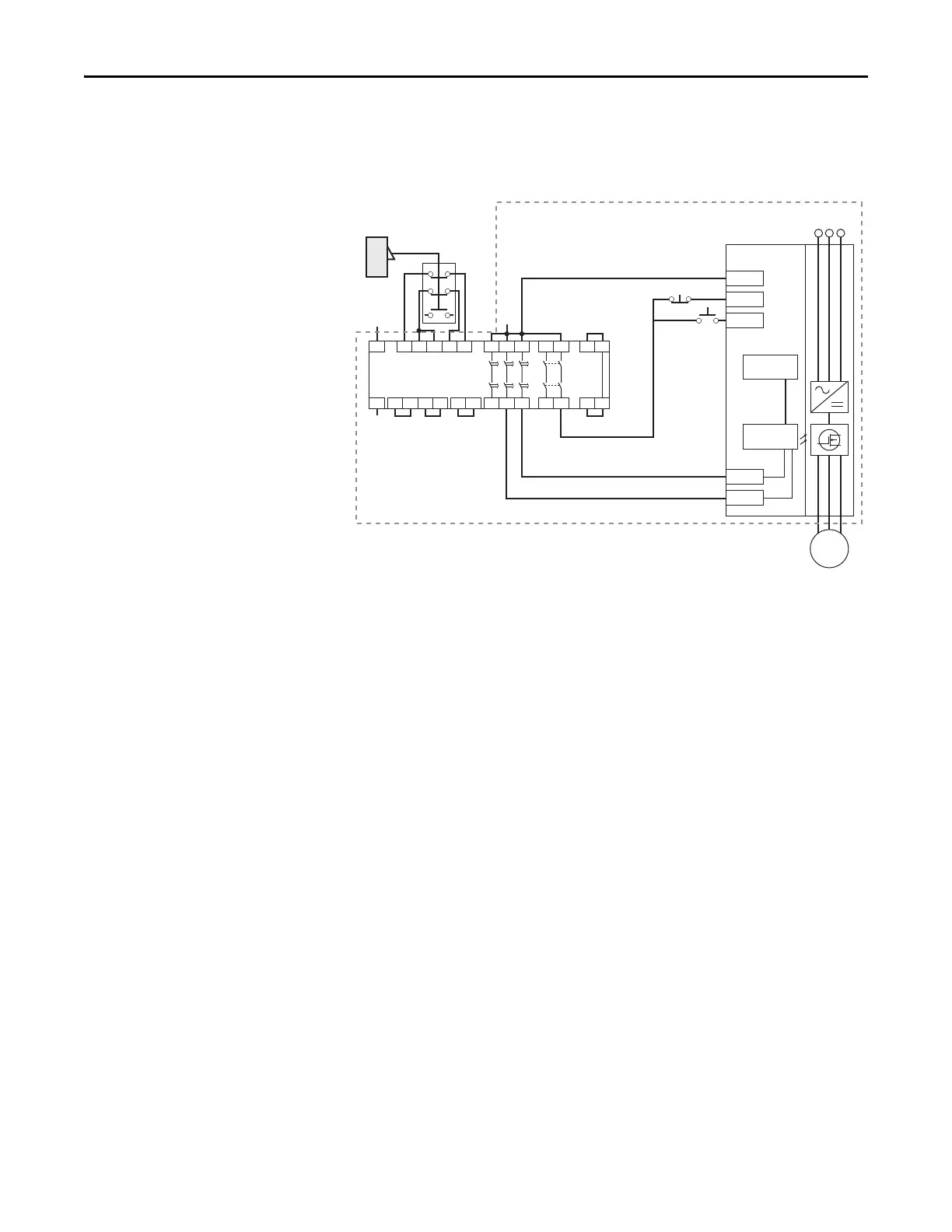
Example 2 – Safe-Torque-Off Connection with Controlled Stop Action,
SIL 2/PL d
Stop Category 1 – Controlled
(1) Enclosure Recommended. External wiring failure modes must be considered as described in EN ISO 13849-2. Enclosure or other
measure to exclude these failure modes should be used.
Circuit Status
Circuit shown with guard door closed and system ready for normal drive
operation.
Operating Principle
This is a dual channel system with monitoring of the Safe-Torque-Off circuit and
drive. Opening the guard door will switch the input circuits (S11-S12 & S21-
S22) to the Minotaur monitoring safety relay unit. The output circuits (13-14)
will issue a Stop command to the drive and cause a controlled deceleration. After
the programmed delay, the timed output circuits (47-48 & 57-58) will cause the
Safe-Torque-Off Enable circuit to trip. If the motor is rotating when the trip
occurs, it will coast to stop. To restart the drive, the Minotaur safety relay must
first be reset followed by a valid start command to the drive.
Fault Detection
A single fault detected on the Minotaur safety input circuits will result in the
lock-out of the system at the next operation and will not cause loss of the safety
function.
A single fault detected on the PowerFlex 525 safety enable redundant inputs will
result in the lock-out of the drive and will not cause the loss of the safety
function.
24V DC
Common
+24V DC
GuardMaster
Trojan
Stop
Start
A1 S21 S11 S52 S12
A2 X1 X2
13 23
14 24
S33
Y2
S34
Y1X3
37 47 57
38 48 58X4
S22
Y39 Y40
Minotaur
MSR138DP
Gate
+24V DC
PF 525
Stop
Start
Gate control
power supply
Gate control
circuit
AC line
input power
S1
S2
M
(1)

 Loading...


