Rockwell Automation Publication 520-UM001G-EN-E - September 2014 37
Installation/Wiring Chapter 1
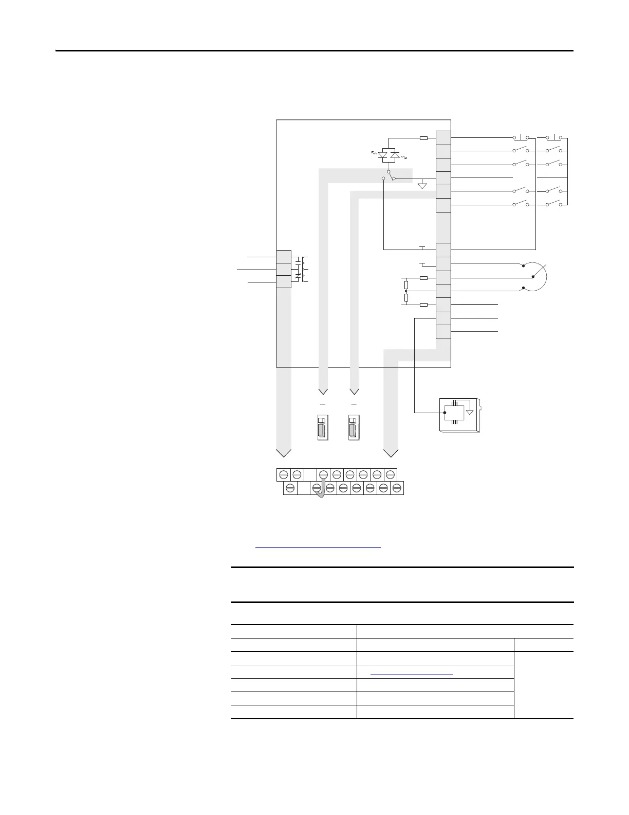
PowerFlex 523 Control I/O Terminal Block
PowerFlex 523 Control I/O Wiring Block Diagram
Control I/O Wiring Block Diagram Notes
(1) See Digital Input Selection for Start Source on page 47 for more information on configuring the digital inputs.
I/O Terminal 01 is always a stop input. The stopping mode is determined by the
drive setting. See the tables below for more information.
Start Method Stop Method
P046, P048, P050 [Start Source x] I/O Terminal 01 Stop Normal Stop
1 “Keypad” Coast Per P045
[Stop Mode]
2 “DigIn TrmBlk” See t062, t063 [DigIn TermBlk xx]
below
3 “Serial/DSI” Coast
4 “Network Opt” Coast
5 “Ethernet/IP”
(1)
(1) Setting is specific to PowerFlex 525 drives only.
Coast
04
05
06
01
02
03
11
12
13
14
15
C1
C2
Digital Common
DigIn TermBlk 05/Pulse
DigIn TermBlk 06
Stop
(1)
DigIn TermBlk 02/
Start/Run FWD
(2)
DigIn TermBlk 03/
Direction/Run REV
R1
R2
Relay N.O.
Relay Common
+24V DC
+10V DC
0-10V Input
Analog Common
4-20mA Input
RJ45 Shield
Comm Common
+24V
+10V
Typical
SNK wiring
Typical
SRC wiring
R1
11
12 13 14 15 C1 C2
R2
R3
01 02 03 04 05 06
Pot must be
1...10 k ohm
2 W min.
SNK
Digital In
DigIn TermBlk 05 Sel
J7J8
Pulse In
SRC Digital
Input
SRCSNK
R3
Relay N.C.
81
RS485
(DSI)

 Loading...


