52 Rockwell Automation Publication 520-UM001G-EN-E - September 2014
Chapter 1 Installation/Wiring
• Maximum motor cable length must not exceed the maximum length
indicated in PowerFlex 520-Series RF Emission Compliance and
Installation Requirements on page 52 for compliance with radio frequency
emission limits for the specific standard and installation environment.
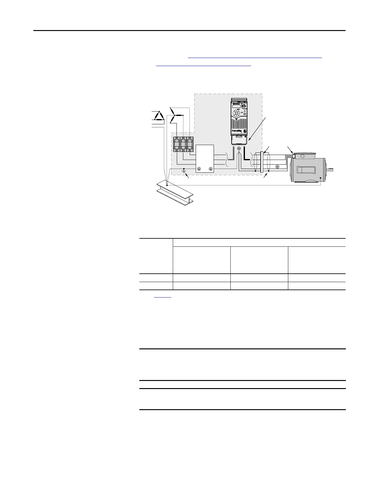
Connections and Grounding
(1) Some installations require a shielded enclosure. Keep wire length as short as possible between the enclosure entry point and the
EMI filter.
Additional Installation Requirements
This section provides information on additional requirements for Class C1 and
C2 installation, such as enclosures and EMC cores.
PowerFlex 520-Series RF Emission Compliance and Installation Requirements
Filter Type Standard/Limits
EN61800-3 Category C1
EN61000-6-3
CISPR11 Group 1 Class B
EN61800-3 Category C2
EN61000-6-4
CISPR11 Group 1 Class A
(Input power ≤ 20 kVA)
EN61800-3 Category C3
(I ≤ 100 A)
CISPR11 Group 1 Class A
(Input power > 20 kVA)
Internal – 10 m (33 ft) 20 m (66 ft)
External
(1)
(1) See Appendix B for more information on optional external filters.
30 m (16 ft) 100 m (328 ft) 100 m (328 ft)
EMC cores are included with:
• drives that have an internal EMC filter (25x-xxxxN114)
• external EMC filter accessory kit (25-RFxxx)
An enclosure, shielded input cable, and EMC cores are not required to meet
class C3 requirements.
R/L1
S/L2
T/L3
U/T1
V/T2
W/T3
EMI ttings and metal conduit
IP 30/NEMA 1/UL Type 1
option kit or EMC kit
Shielded enclosure
(1)
Building structure steel
Enclosure ground connection
EMI lter
L1'
L2'
L3'
L1
L2
L3
Shielded motor cable

 Loading...


