EasyManua.ls Logo

Allen-Bradley PowerFlex 520 Series User Manual

Allen-Bradley PowerFlex 520 Series
244 pages
To Next Page IconTo Next Page
To Previous Page IconTo Previous Page
Page #89 background image
Rockwell Automation Publication 520-UM001G-EN-E - September 2014 89
Programming and Parameters Chapter 3
Terminal Block Group (continued)
t087 [EM Brk On Delay] Related Parameter(s): P045
Sets the time the drive remains at minimum frequency (after releasing the brake coil relay) before stopping if EM Brake Control Mode is enabled with P045 [Stop Mode].
Values Default: 2.00 s
Min/Max: 0.00/10.00 s
Display: 0.01 s
Frequency
Time
[Minimum Freq]
[EM Brk O Delay]
[EM Brk On Delay]
Stop
commanded
Start
commanded
EM Brk
de-energized (On)
Drive stopsEM Brk
energized (O)
Ramp accel
Ramp decel
t088 [Analog Out Sel] Related Parameter(s): t090
PowerFlex 525 only.
The 0-10V, 0-20 mA or 4-2 0 mA analog output can be used to provide a signal proportional to several drive conditions. This parameter also selects which analog calibration parameters
to use.
Values Default: 0
Min/Max: 0/23
Display: 1
PF 525
Options Output Range Minimum Output Value Maximum Output Value =
t089 [Analog Out High]
Filter
(1)
(1) Filter A is a single pole digital filter with a 162 ms time constant. Given a 0...100% step input from a steady state, the output of Filter A takes 500 ms to get to 95% of maximum, 810 ms to get to 99%,
and 910 ms to get to 100%.
Related
Parameter
0 “OutFreq 0-10” 0-10V 0V = 0 Hz [Maximum Freq] None b001
1 “OutCurr 0-10” 0-10V 0V = 0 A 200% Drive Rated Current Filter A b003
2 “OutVolt 0-10” 0-10V 0V = 0 V 120% Drive Rated Output Volts None b004
3 “OutPowr 0-10” 0-10V 0V = 0 kW 200% Drive Rated Power Filter A b017
4 “OutTorq 0-10” 0-10V 0V = 0 A 200% Drive Rated Current Filter A d382
5 “TstData 0-10” 0-10V 0V = 0000 65535 (Hex FFFF) None
6 “Setpnt 0-10” 0-10V 0V = 0% 100.0% Setpoint setting None t090
7 “DCVolt 0-10” 0-10V 0V = 0V 100.0% of trip value None b005
8 “OutFreq 0-20” 0-20 mA 0 mA = 0 Hz [Maximum Freq] None b001
9 “OutCurr 0-20” 0-20 mA 0 mA = 0 A 200% Drive Rated Current Filter A b003
10 OutVolt 0-20” 0-20 mA 0 mA = 0 V 120% Drive Rated Output Volts None b004
11 OutPowr 0-20” 0-20 mA 0 mA = 0 kW 200% Drive Rated Power Filter A b017
12 “OutTorq 0-20” 0-20 mA 0 mA = 0 A 200% Drive Rated Current Filter A d382
13 “TstData 0-20” 0-20 mA 0 mA = 0000 65535 (Hex FFFF) None
14 “Setpnt 0-20” 0-20 mA 0 mA = 0% 100.0% Setpoint setting None t090
15 “DCVolt 0-20” 0-20 mA 0 mA = 0V 100.0% of trip value None b005
16 OutFreq 4-20” 4-20 mA 4 mA = 0 Hz [Maximum Freq] None b001
17 “OutCurr 4-20” 4-20 mA 4 mA = 0 A 200% Drive Rated Current Filter A b003
18 OutVolt 4-20” 4-20 mA 4 mA = 0 V 120% Drive Rated Output Volts None b004
19 OutPowr 4-20” 4-20 mA 4 mA = 0 kW 200% Drive Rated Power Filter A b017
20 “OutTorq 4-20” 4-20 mA 4 mA = 0 A 200% Drive Rated Current Filter A d382
21 “TstData 4-20” 4-20 mA 4 mA = 0000 65535 (Hex FFFF) None
22 “Setpnt 4-20” 4-20 mA 4 mA = 0% 100.0% Setpoint setting None t090
23 “DCVolt 4-20” 4-20 mA 4 mA = 0V 100.0% of trip value None b005

Table of Contents

Question and Answer IconNeed help?

Do you have a question about the Allen-Bradley PowerFlex 520 Series and is the answer not in the manual?

Allen-Bradley PowerFlex 520 Series Specifications

General IconGeneral
BrandAllen-Bradley
ModelPowerFlex 520 Series
CategoryDC Drives
LanguageEnglish

Summary

Preface

Overview

Provides a general introduction to the PowerFlex 520-Series Adjustable Frequency AC Drive.

General Precautions

Details important safety guidelines and warnings for handling and installing the drive.

Catalog Number Explanation

Explains the structure and meaning of the PowerFlex 520-series drive catalog numbers.

Chapter 1 Installation/Wiring

Mounting Considerations

Details information on mounting and wiring the PowerFlex 520-series drives.

AC Supply Source Considerations

Provides guidelines for connecting the AC supply source to the PowerFlex 520-series drives.

General Grounding Requirements

Outlines the requirements for safely grounding the PowerFlex 520-series drives.

Fuses and Circuit Breakers

Provides recommendations for input fuses and circuit breakers for PowerFlex 520-Series drives.

Power Wiring

Details the procedures and guidelines for connecting power wiring to the drive.

I/O Wiring

Provides important points and recommendations for wiring the drive's I/O.

Control I/O Terminal Block

Details the wire specifications for the control I/O terminal block.

Start and Speed Reference Control

Explains how to select and configure start and speed reference sources for the drive.

CE Conformity

Details the PowerFlex 520-series drives compliance with CE directives and standards.

Chapter 2 Start Up

Prepare for Drive Start-Up

Provides a task list for preparing the drive for initial start-up procedures.

Viewing and Editing Parameters

Illustrates basic keypad navigation and how to program a parameter.

Drive Programming Tools

Lists recommended software tools for drive configuration and setup.

Smart Start-Up with Basic Program Group Parameters

Describes configuration of commonly used parameters for simple and efficient drive setup.

Chapter 3 Programming and Parameters

Parameter Groups

Lists and organizes drive parameters for quick access based on function.

Basic Display Group

Details parameters for viewing common drive operating conditions.

Basic Program Group

Details commonly used programmable functions for drive setup.

Terminal Block Group

Details parameters related to programmable terminal functions.

Communications Group

Details parameters for programmable communication functions.

Fault and Diagnostic Group

Lists codes for specific fault conditions and diagnostic information.

AppView Parameter Groups

Groups parameters for specific applications for quick access.

Chapter 4 Troubleshooting

Drive Status

Describes how the drive's condition is monitored and indicated.

Faults

Defines faults as conditions that stop the drive and categorizes them.

Fault Descriptions

Provides a list and description of drive faults with corresponding actions.

Common Symptoms and Corrective Actions

Lists common drive symptoms and their corrective actions for troubleshooting.

Appendix A Supplemental Drive Information

Certifications

Lists the certifications and compliance standards for the PowerFlex 520-series drives.

Environmental Specifications

Details operating and storage conditions for the drives.

Technical Specifications

Provides detailed electrical and control specifications for the drives.

Power Specifications

Lists estimated watts loss for various drive ratings.

Appendix B Accessories and Dimensions

Product Selection

Provides guidance for selecting the correct PowerFlex 520-series drive based on ratings.

PowerFlex 520-Series Drive Ratings

Details the power ratings, output current, and catalog numbers for drive models.

Human Interface Module (HIM) Option Kits and Accessories

Lists available option kits and accessories for the Human Interface Module.

Optional Accessories and Kits

Details installation procedures for optional accessories like communication adapters.

Appendix C RS485 (DSI) Protocol

Network Wiring

Describes the network wiring for connecting PowerFlex 520-series drives via RS485.

Parameter Configuration

Lists parameters used to configure the drive for operation on a DSI network.

Supported Modbus Function Codes

Lists the Modbus function codes supported by the PowerFlex 520-series drives.

Appendix D Velocity StepLogic, Basic Logic and Timer/Counter Functions

Velocity StepLogic Using Timed Steps

Explains how to configure Velocity StepLogic using timed steps for motor control.

Timer Function

Describes how digital inputs and outputs control the timer function.

Counter Function

Details how digital inputs and outputs control the counter function.

Appendix E Encoder/Pulse Train Usage and Position StepLogic Application

Encoder and Pulse Train Usage

Explains the use of pulse train input and optional encoder cards for drive functions.

Positioning Overview

Provides an overview of the position regulator for various applications.

Common Guidelines for All Applications

Offers general guidelines for configuring the position regulator for different applications.

Positioning Operation

Details how to operate the position regulator based on different modes.

Appendix F PID Set Up

PID Loop

Explains the built-in PID control loops and how they maintain process feedback.

Exclusive Control

Describes the configuration where PID Output becomes the entire frequency command.

Trim Control

Details how PID Output is added to the Speed Reference for trimming.

PID Reference and Feedback

Explains how to select PID reference and feedback sources.

Guidelines for Adjusting the PID Gains

Provides step-by-step guidance for adjusting PID gains for optimal performance.

Appendix G Safe-Torque-Off Function

PowerFlex 525 Safe-Torque-Off Overview

Provides an overview of the Safe-Torque-Off function and its safety compliance.

Important Safety Considerations

Highlights critical safety responsibilities for the system user.

Enabling PowerFlex 525 Safe-Torque-Off

Details the procedure for enabling the Safe-Torque-Off function on the drive.

Verify Operation

Describes how to test the safety function after initial setup and periodically.

Appendix H EtherNet/IP

Establishing A Connection With EtherNet/IP

Provides basic information on setting up an EtherNet/IP connection.

Appendix I Control Diagrams

Induction Motor Tuning Diagrams

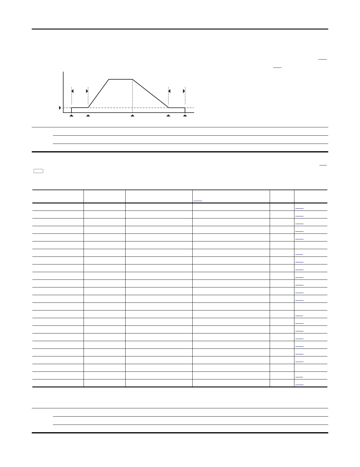
Presents diagrams illustrating motor tuning for speed control.

Adjusting Speed Control Parameters

Provides guidance on adjusting speed control parameters for motor tuning.

Related product manuals