10 Rockwell Automation Publication 520-QS001A-EN-E - March 2014
PowerFlex 520-Series Adjustable Frequency AC Drive
I/O Wiring
See the PowerFlex 520-Series Adjustable Frequency AC Drive User Manual, publication 520-UM001 for
recommendations on maximum power and control cable length.
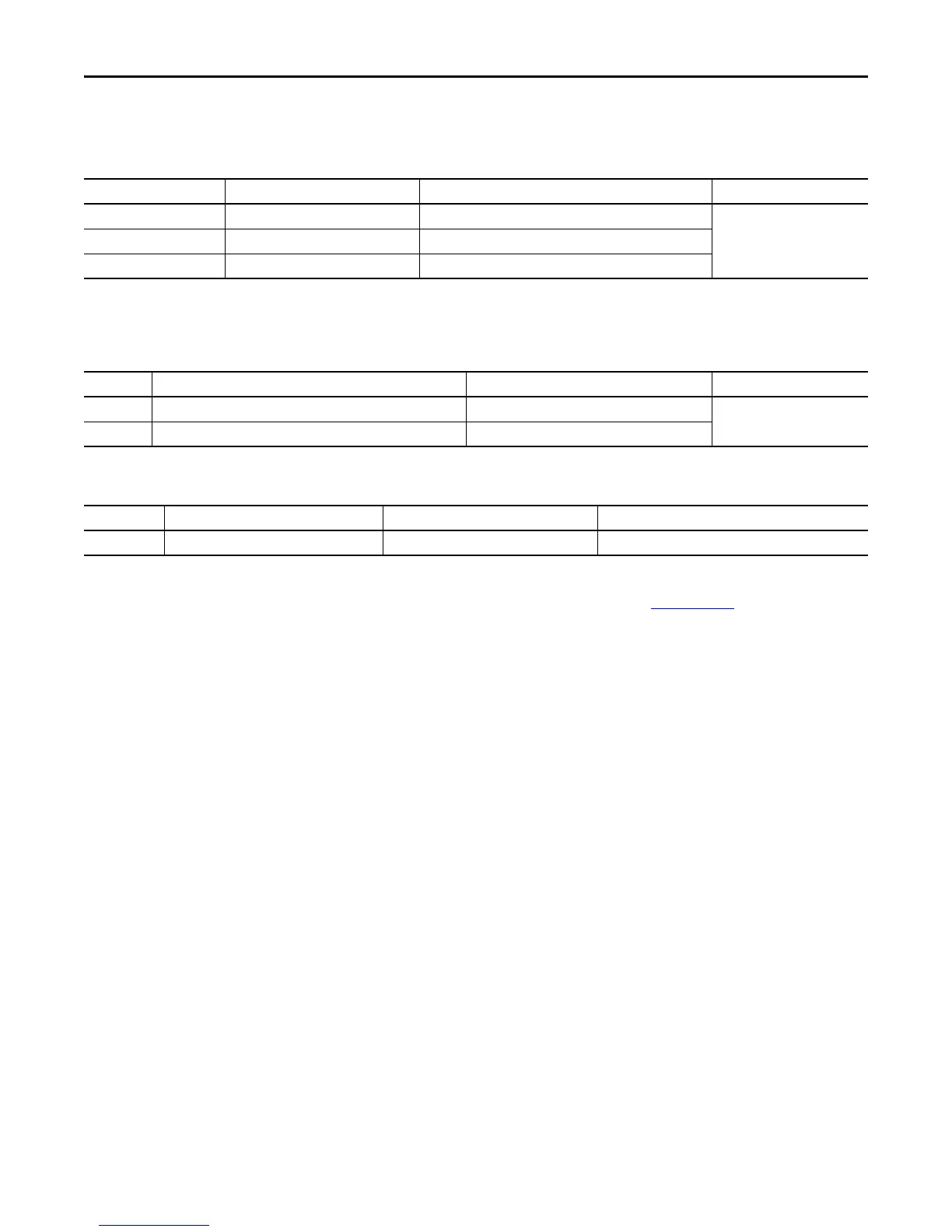
Recommended Signal Wire
Signal Type/ Where Used Belden Wire Type (or equivalent)
(1)
(1) Stranded or solid wire.
Description Minimum Insulation Rating
Analog I/O & PTC 8760/9460 0.750 mm
2
(18 AWG), twisted pair, 100% shield with drain
(2)
(2) If the wires are short and contained within a cabinet which has no sensitive circuits, the use of shielded wire may not be necessary, but is always recommended.
300V,
60 °C (140 °F)
Remote Pot 8770 0.750 mm
2
(18 AWG), 3 conductor, shielded
Encoder/Pulse I/O 9728/9730 0.196 mm
2
(24 AWG), individually shielded pairs
Recommended Control Wire for Digital I/O
Type Wire Type(s) Description Minimum Insulation Rating
Unshielded Per US NEC or applicable national or local code – 300V,
60 °C (140 °F)
Unshielded Multi-conductor shielded cable such as Belden 8770 (or equivalent) 0.750 mm
2
(18 AWG), 3 conductor, shielded.
Control I/O Terminal Block Wire Specifications
Frame Maximum Wire Size
(1)
(1) Maximum/minimum sizes that the terminal block will accept – these are not recommendations.
Minimum Wire Size
(1)
Torque
A...E 1.3 mm
2
(16 AWG) 1.3 mm
2
(16 AWG) 0.71...0.86 Nm (6.2...7.6 lb-in.)

 Loading...


