Connector Descriptions C-9
Table C.J PowerFlex 700H and 700S Interface Board to ASIC Board on Power
Structure #2 Fiber Optic Connections
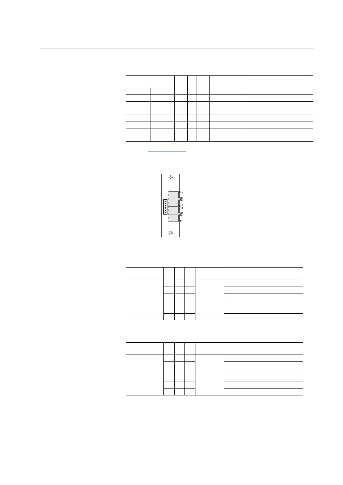
Figure C.6 Termination Points on ASIC Feedback Boards
Table C.K ASIC Feedback Board on Power Structure #1 to ASIC Board on Power
Structure #1 Connections
Table C.L ASIC Feedback Board on Power Structure #2 to ASIC Board on Power
Structure #2 Connections
Interface Board Fiber
Optic Connector
Type to Type
ASIC Board
Fiber Connector
(1)
(1)
Refer to Figure C.1 on page C-2 for ASIC board fiber-optic connectors.
Description: Reference to ASIC
Board700H 700S
H11 J19 TX . . . RX H1 Gate_Enable
H12 J20 TX . . . RX H2 U_Gate
H13 J21 TX . . . RX H3 V_Gate
H14 J22 TX . . . RX H4 W_Gate
H15 J23 TX . . . RX H5 A/D Convert
H16 J25 TX . . . RX H6 VBUS_RX
H17 J24 RX . . . TX H7 VBUS_TX
ASIC Feedback
Board Connector Pin to Pin
ASIC Board
Connector Description: Reference to ASIC Board
X900 1 . . . 1 X26 PHU
2. . .2 PHV
3. . .3 PHW
4. . .4 Trip_Out
5. . .5 +5V
6. . .6 +5V
ASIC Feedback
Board Connector Pin to Pin
ASIC Board
Connector Description: Reference to ASIC Board
X900 1 . . . 1 X26 PHU
2. . .2 PHV
3. . .3 PHW
4. . .4 Trip_Out
5. . .5 +5V
6. . .6 +5V
H900
H901
H902
H903
X900

 Loading...


