104 Rockwell Automation Publication 20Y-TG001C-EN-P - April 2017
Appendix B Schematic Diagrams
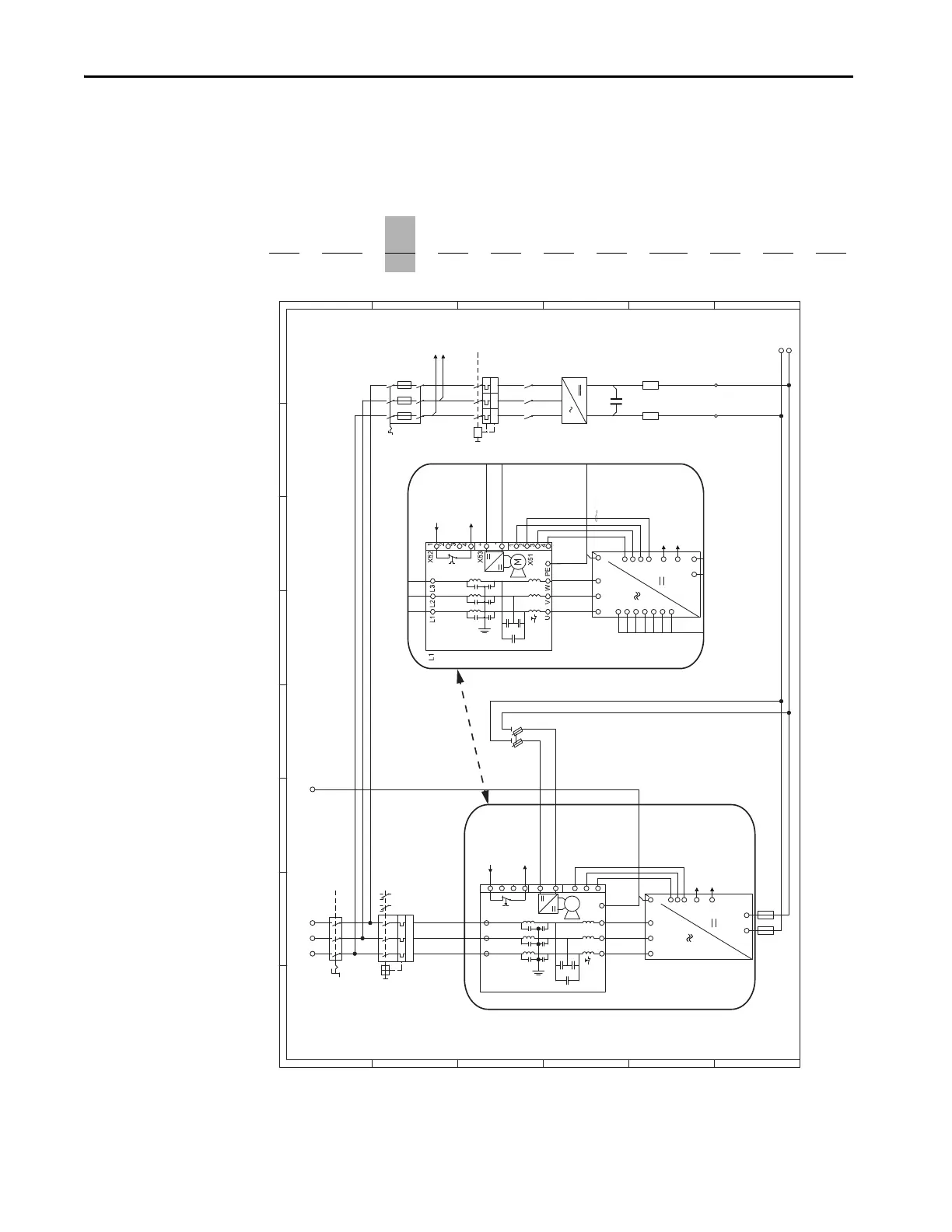
System Schematics for Frame
10 AFE in IP21 Rittal
Enclosure
The following system schematics are for the AFE Frame 10 in an IP21 Rittal
enclosure. The PowerFlex AFE catalog number has an enclosure code of A as
shown in the example catalog string. For other enclosure designs, contact the
supplier of the system for the system schematics.
Position
1…3 4 5…7
8 9 10111213 141516
20Y D 460
A0 ANNA NA0
a bc
def ghi j kl
1
2
I >> I >> I >>
3
4
5
12 14 96 98
11 95
1 3
2 4
Q/1 SY
6
1
2
3
4
5
6
L1
+
L2 L3
-
1
2
1
2
L1 L2 L3
X52
Older Version
Newer Version
X53
X51
UVW
M
1
2
3
4
+
-
1
3
4
PE
UVW
B+ B-
PE
1
2
1
2
3
L1 L2 L3
PE
B+
B-
-Q1
-Q0
/7-7B TF+1
TF11 /7-6C
AP1 /7-2D
OF1 /7-2D
-F6
L1 /8-1A
L2 /8-1A
-K6
-V6
-R6.1 -R6.2
-Q5
-F2.1
1100A
-F2.2
1100A
-L1
-F11
8A
-U1
+-X6 -
-C1
/11-2E
12345678
A
B
C
D
E
F
A
B
C
D
E
F
MAIN CIRCUIT
1
2
3
4
5
6
1
2
3
4
5
13
3
5
6
246
I >I >I >
/7-7B TF+1
TF11 /7-6C
UVW
DC+
24V DC
–
+
DC–
PE
1
2
3
– DC Bus
AP1 /7-2D
1
2
3
X3
4
5
6
7
OF1 /7-2D
-U1
X70 Wire
Connected to -DC
secondary side of
fan inverter fuses
in power structure
(CAUTION: High
Voltage -DC bus
potential)
Figure 27 - Frame 10 in IP21 Rittal Enclosure – Sheet 6 (400/480V and 600/690V)
 Loading...


