46 Rockwell Automation Publication 20Y-TG001C-EN-P - April 2017
Chapter 4 AFE Power Structure Component Section
Remove Protective Covers from the Power Structure
To access the internal components of the power structure, you must remove the
protective covers.
To remove the protective covers from the power structure, follow these steps.
1. Remove power from the AFE.
See Remove Power from the AFE
on page 37.
2. If present, remove the protective barriers.
See Remove AFE Protective Barriers
on page 44.
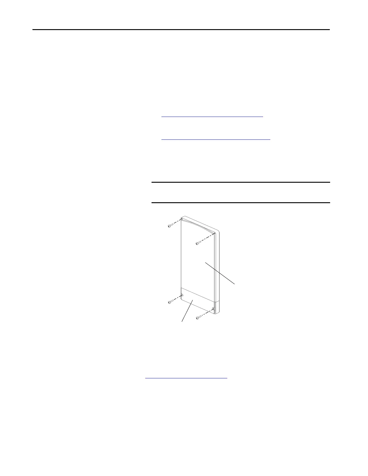
3. Remove the four M5 Pozidriv screws that secure the protective front
cover and terminal cover to the power structure.
4. Remove the covers.
Install Protective Covers on the Power Structure
Install the protective covers on the power structure in reverse order of removal.
See Torque Specifications
on page 36.
Remove the Gate Driver Circuit Board
There is one gate driver circuit board on the front of the power structure.
To remove the gate driver circuit board, follow these steps.
IMPORTANT Remove only the terminal cover to gain access to the cooling fan
connections.
Terminal Cover
Front Cover