28 Rockwell Automation Publication 20Y-TG001C-EN-P - April 2017
Chapter 3 Component Test Procedures
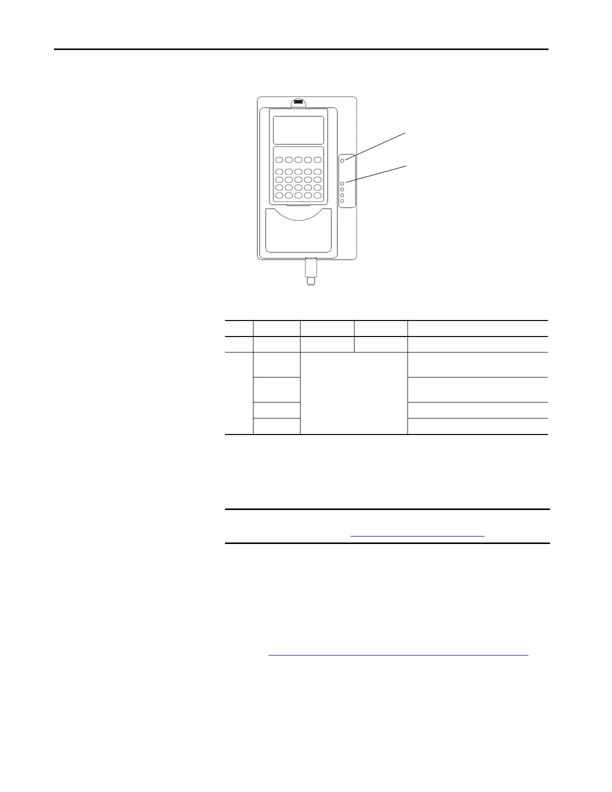
View the Status Indicators
This section describes the status indicators.
Table 1 - AFE Status Indicator Descriptions
Perform a Visual Inspections
Inspect the Cooling Tunnel
To inspect the cooling tunnel, follow these steps.
1. Remove the main cooling fan from the bottom of the power structure.
See Remove and Install the Power Structure Fan System on page 52
.
2. Inspect the tunnel.
Clean the heatsink and tunnel if necessary.
Item Name Color State Description
1 PWR (power) Green Steady Illuminates when power is applied to the AFE.
2PORT
(1)
(1) These indicators operate only when a 20-COMM-X communication adapter is installed in the AFE and operating on the
connected network.
See the Communication Adapter
User Manual, publication 20COMM-
UMxxx
Status of DPI™ port internal communication (if
present).
MOD
(1)
Status of communication adapter (when
installed).
NET A
(1)
Status of network (if connected).
NET B
(1)
Status of secondary network (if connected).
IMPORTANT Always remove power from the Active Front End before performing visual
inspections. See Remove Power from the AFE on page 37
.
 Loading...


