Home
Allen-Bradley
Controller
PowerFlex AFE
Allen-Bradley PowerFlex AFE User Manual
5
of 1
of 1 rating
134 pages
Give review
Manual
Specs
To Next Page
To Next Page
To Previous Page
To Previous Page
Loading...
Rockwell Automation
Publi
cation 20Y-TG0
01
C-EN-P - Apri
l 2017
77
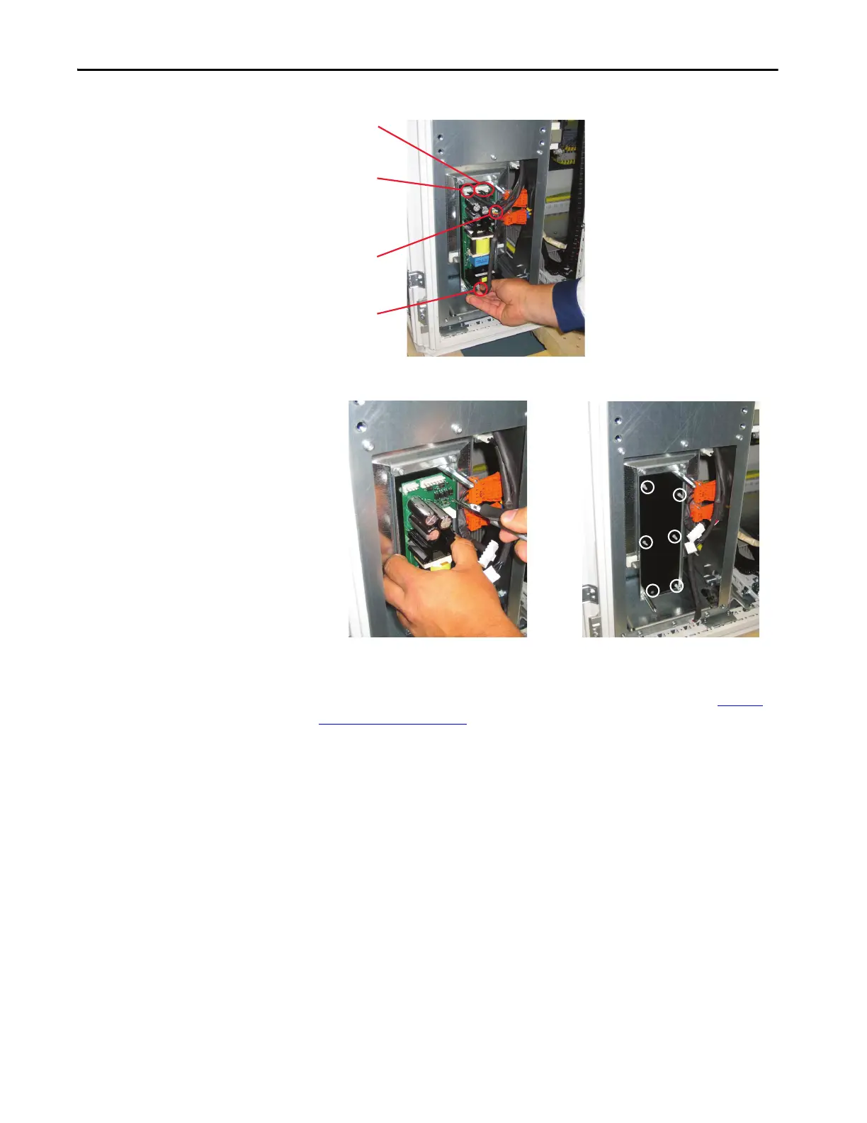
L
C
L Filter Co
mponent Sec
tion
Chapter 7
5.
Remove the six fastene
rs tha
t secure t
he DC
-to
-DC p
ower s
upply
.
Install the L
CL Filter F
an DC
Pow
e
r
S
u
p
p
l
y
I
ns
t
all
t
he
DC-t
o-DC
po
we
r su
ppl
y i
n
r
eve
rse
or
der
o
f r
emo
v
al.
See
To
r
q
u
e
Specification
s
on pa
g
e
36
.
X8
X3
X1
X4
76
78
Table of Contents
Default Chapter
3
Table of Contents
3
Intended Audience
7
Preface
7
Summary of Changes
7
What Is in this Manual
7
What Is Not in this Manual
7
Additional Resources
8
Additional Support Available on the Internet
8
Spare Parts
8
General Precautions for Class 1 Light-Emitting Diode Product
9
Chapter 1 Troubleshooting and Error Codes Create Fault Reports
12
Create Fault Reports
12
Powerflex Active Front End Faults
12
Common Symptoms and Corrective Actions
17
Chapter 2
19
Main Component Sections
19
Main Component Locations
20
Main Bus Bar/Cable Locations
21
AFE in IP21 Rittal Enclosure
22
Main Component Sections
22
Main Component Locations
23
Bus Bar Locations
24
AFE in IP00 Open Chassis Configuration
25
AFE in IP20 2500 MCC Style Enclosure
19
Chapter 3 Perform a Visual Inspections
28
Inspect the Cooling Tunnel
28
Component Test Procedures View the Status Indicators
28
Inspect the Power Structure
29
View the Status Indicators
28
Perform Forward and Reverse Biased Diode Tests for Power Structure
29
Check Fiber-Optic Connections
31
Perform Gate Driver Board Resistance Measurements
33
Check the AFE Power Structure Fan Inverter Fuses
34
Chapter 4
36
Torque Specifications
36
Understand Torque Figures in Assembly Diagrams
36
Remove Power from the AFE
37
Control Frame Access Procedures
38
Remove the DPI Interface Assembly
38
Install the DPI Interface Assembly
39
Remove the I/O Circuit Boards and Control Board
39
Install the I/O Circuit Boards and Control Board
40
Remove the Fiber-Optic Adapter Circuit Board
40
Install the Fiber-Optic Adapter Circuit Board
42
Remove the Control Frame
43
Rittal Enclosure)
43
Replace the Control Frame
43
Power Structure Access Procedures
44
Remove AFE Protective Barriers
44
Install the AFE Protective Barriers
45
Remove the AFE Airflow Plate
45
Install the AFE Airflow Plate
45
Remove Protective Covers from the Power Structure
46
Install Protective Covers on the Power Structure
46
Remove the Gate Driver Circuit Board
46
Install the Gate Driver Circuit Board
48
Remove the ASIC Circuit Board
48
Install the ASIC Circuit Board
51
Remove and Install the Power Structure Fan System
52
Remove the Power Structure from the Enclosure
52
Install the Power Structure in the Enclosure
55
Remove the Power Module from the Power Structure
55
Install the Power Module on the Power Structure
61
Remove the Power Structure DC Bus Capacitors
61
Install the Power Structure DC Bus Capacitors
62
Power Structure
62
AC Line Switchgear Component Section
63
AFE in IP20 2500 MCC Style Enclosure
64
AFE in IP21 Rittal Enclosure
64
Chapter 5
64
Precharge Component Section
65
Chapter 6 Precharge Functions
66
Replace the Precharge Fuse
66
Supply (T10)
67
For AFE in IP20 2500 MCC Style Enclosure
67
For AFE in IP21 Rittal Enclosure
68
Test the Control Transformer (T4) and 24V DC Power
67
Replace the Precharge Bridge
70
Terminals
70
Test the Precharge Bridge by Using the Power Structure
70
Replace the Precharge Resistor Assembly
71
AFE in IP20 2500 MCC Style Enclosure
71
AFE in IP21 Rittal Enclosure
72
Rockwell Automation Publication 20Y-TG001C-EN-P - April
73
Test the Precharge Resistor
71
Chapter 7
74
Install the LCL Filter Protective Barrier
74
Remove the LCL Filter Protective Barrier
74
Replace the LCL Filter DC Fan Fuses
74
Remove the LCL Filter Fan DC Power Supply
75
Install the LCL Filter Fan DC Power Supply
77
Remove the LCL Filter
78
From the IP20 2500 MCC Style Enclosure
79
From the IP21 Rittal Enclosure
80
Replace the LCL Filter Fan
78
Install the LCL Filter in the Enclosure
81
Overview
83
Chapter 8 Fuse Replacement Guidelines
84
Chapter 9 Technical Support
87
Before You Apply Power to the AFE
88
Appendix A
89
Service Tools
89
Software Tools
89
Appendix B Frame 10 Circuit Board Connections
91
Frame 10 Power Module Circuitry
92
Frame 10 Power Structure Main Fan Connections
93
Control Wiring Diagram for Frame 10 in IP20 2500
94
MCC Style Enclosure
94
MCC Style Enclosure
96
Control Wiring Diagram for Frame 10 in IP21 Rittal Enclosure
103
System Schematics for Frame 10 AFE in IP21 Rittal Enclosure
104
Circuit Board Connections
113
Appendix C Hardware Connections
116
AFE Power Structure Assembly
118
Appendix D
122
LCL Filter Assembly (Used in IP20 and IP21 Enclosures)
122
Precharge Assembly
124
AC Line Switchgear
126
Data to Collect
129
Typical Transformer Winding Types
130
Index
131
5
Based on 1 rating
Ask a question
Give review
Questions and Answers:
Need help?
Do you have a question about the Allen-Bradley PowerFlex AFE and is the answer not in the manual?
Ask a question
Allen-Bradley PowerFlex AFE Specifications
General
Brand
Allen-Bradley
Model
PowerFlex AFE
Category
Controller
Language
English
Related product manuals
PowerFlex 20-750-APS
302 pages
Allen-Bradley PowerFlex 4
108 pages
Allen-Bradley PowerFlex 4M
118 pages
Allen-Bradley PowerFlex 40
218 pages
Allen-Bradley PowerFlex 525
244 pages
Allen-Bradley PowerFlex 523
244 pages
Allen-Bradley PowerFlex 755
354 pages
Allen-Bradley PowerFlex 527
354 pages
Allen-Bradley PowerFlex 400
218 pages
Allen-Bradley PowerFlex 755 IP00
78 pages
PowerFlex 20-750-S1
302 pages
PowerFlex 750 Series
50 pages
 Loading...


