Rockwell Automation Publication 20Y-TG001C-EN-P - April 2017 119
Disassembly/Assembly Diagrams and Spare Parts Appendix D
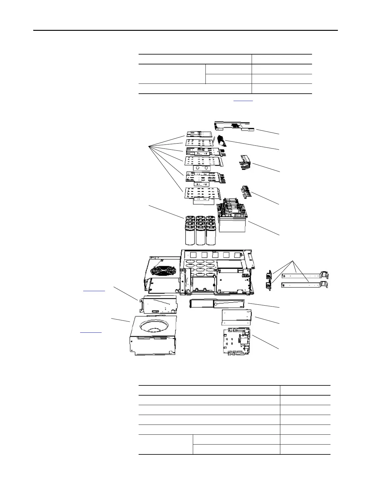
Figure 39 - AFE Power Structure Assembly Internal Components
Power structure 400/480V (460 A) SK-Y1-PWRMOD-D460
600/690V (325 A) SK-Y1-PWRMOD-E325
Maintenance stand 20-MAINSTD
(1) For additional AC fan system information, see publication PFLEX-IN029.
Table 13 - AFE Power Structure Assembly External Component Part Numbers (Continued)
Part Name Cat. No.
DC Bus Bar Assembly
Power Bus Bar
EMC Cover
Gate Drive Board
Snubber Capacitor
Assembly
Airflow Channel
Power Module
(IGBTs)
Electrolytic Capacitors
Balancing Resistors
DC Bus Bar Terminal Assembly
Screening Plate
AC Fan Inverter Assembly or
DC Fan Power Supply
(see PowerFlex 700H, 700S, and
700AFE Drive Fan Systems,
publication PFLEX-IN029
, for
complete details)
Main Cooling Fan Assembly
(see PowerFlex 700H, 700S, and
700AFE Drive Fan Systems,
publication PFLEX-IN029
, for
complete details)
Table 14 - AFE Power Structure Assembly Internal Component Part Numbers
Part Name Cat. No.
Airflow channel N/A
Balancing resistors N/A
DC bus bar assembly N/A
DC bus bar terminal assembly N/A
Electrolytic capacitors ELKO 3300 µF 420V for 400/480V AFE 20-PP01005
ELKO 5600 µF 420V for 600/690V AFE 20-PP01099
 Loading...


