18 /
COMMISSIONING
Supply pressure check
1. Closethegasvalve.
2. Loosen screw “a” and insert the pressure gauge
connectionpipeintothepipetap.
3. Openthegasvalve.
4. SwitchtheapplianceONbyopeningaDHWtap.
Thesupplypressureshouldcorrespondtothevalue
establishedinrelationtothetypeofgasforwhichthe
applianceisdesigned.
5. SwitchtheapplianceOFFbyclosingtheDHWtap.
6. Closethegasvalve.
7. Whenthecheckisover,tightenscrew“b”andmake
sureitissecurelyinplace.
8. Openthegasvalveandcheckthetightnessofthe
screw.
WARNING!!
Should the power pressure not
correspond to what indicated on the Gas
Summary Table, DO NOT ACTIVATE THE
DEVICE.
1 2
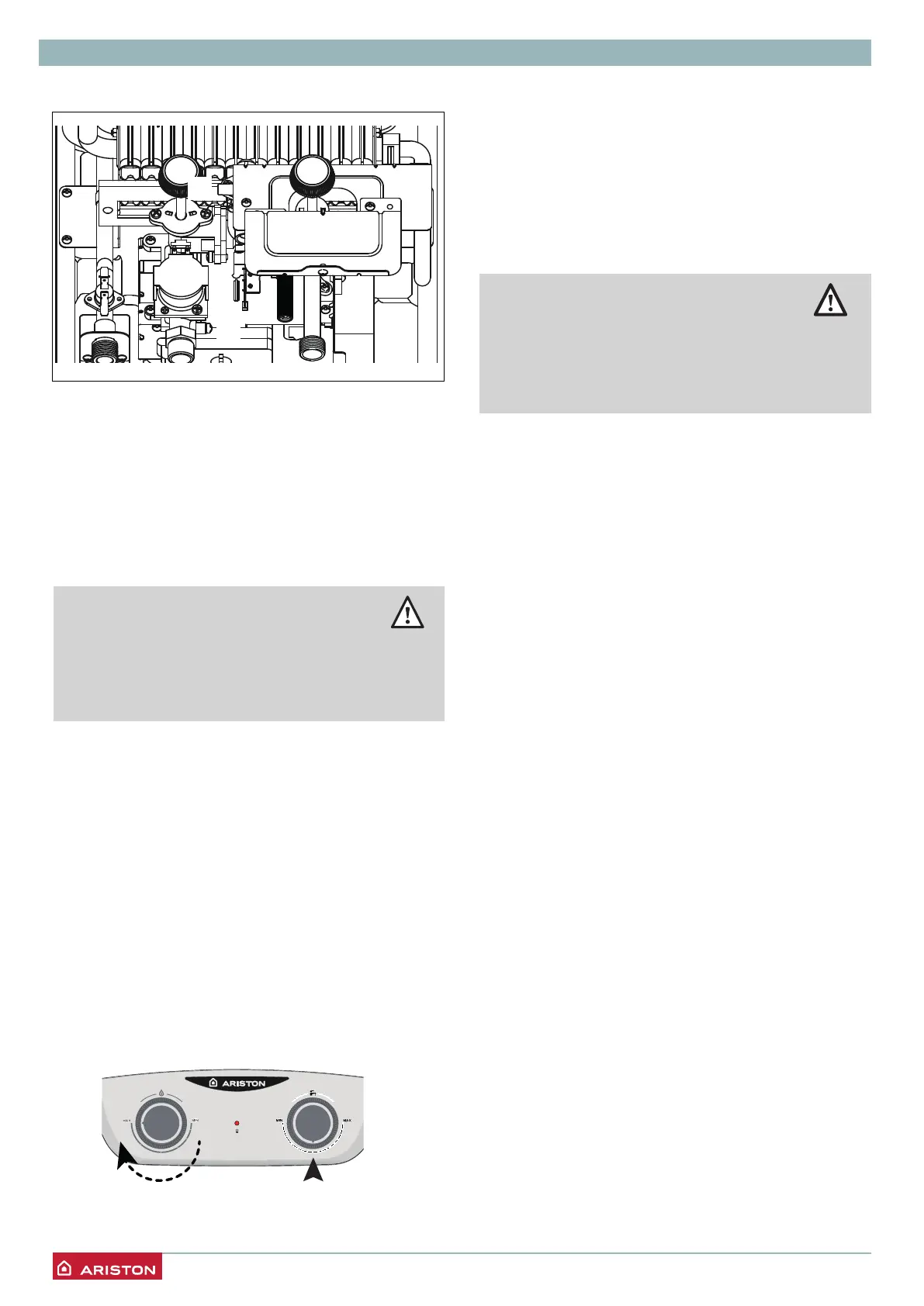
Checking the gas settings
Checking the maximum pressure
(see the Gas setting table)
1. Closethegasvalve
2. Loosen screw “b” and insert the manometer
connectionpipeintothepipetap.
3. Openthegasvalve
4. Openonehotwatertap.
5. Turntheknob1onMAXposition,(Applianceforced
tomaximumpower).
Turntheknob3turnincentralposition.
6. Checkthemaximumburnerpressure.
a
b
WARNING!!
Should the maximum burner pressure not
correspond to what indicated on the Gas
Summary Table, DO NOT ACTIVATE THE
DEVICE.
The pressure should correspond to the value
establishedinrelationtothetypeofgasforwhichthe
applianceisdesigned.
7. SwitchtheapplianceOFFbyclosingtheDHWtap.
8. Check isover,closethe gas valveand tighten the
screw“b”,makesureitissecurelyinplace
Checkthetightnessofthescrew.
 Loading...