1-18
Chapter 1: Product introduction
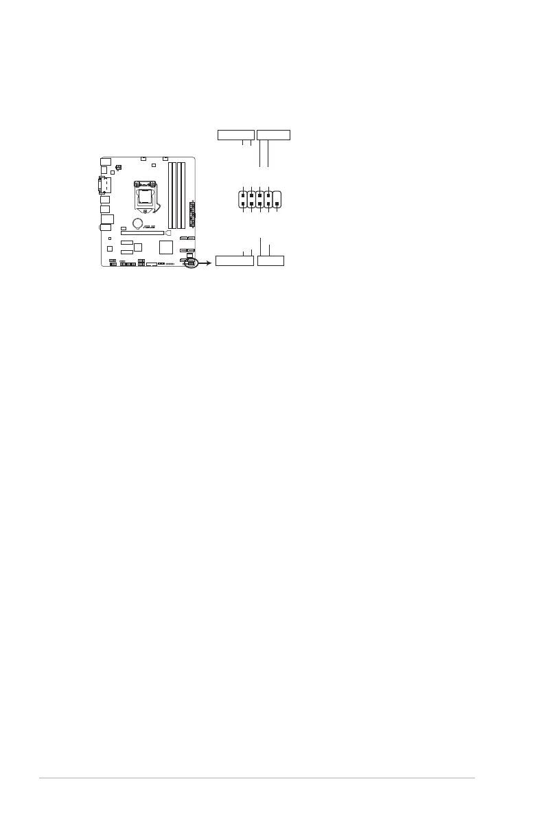
8. System panel connector (10-1 pin F_PANEL)
Thisconnectorsupportsseveralchassis-mountedfunctions.
B150M-A D3
PIN 1
PWR BTN
PWR_LED+
PWR_LED-
PWR
GND
HDD_LED+
HDD_LED-
Ground
HWRST#
(NC)
F_PANEL
+PWR LED
+HDD_LED RESET
B150M-A D3 System panel connector
• SystempowerLED(2-pinPWRLED)
This2-pinconnectorisforthesystempowerLED.ConnectthechassispowerLED
cabletothisconnector.ThesystempowerLEDlightsupwhenyouturnonthesystem
power,andblinkswhenthesystemisinsleepmode.
•
Hard disk drive activity LED (2-pin +HDLED)
This2-pinconnectorisfortheHDDActivityLED.ConnecttheHDDActivityLEDcable
tothisconnector.TheHDLEDlightsuporasheswhendataisreadfromorwrittento
theHDD.
•
ATX power button/soft-off button (2-pin PWRBTN)
This connector is for the system power button.
•
Reset button (2-pin RESET)
This 2-pin connector is for the chassis-mounted reset button for system reboot without
turning off the system power.
 Loading...