EasyManuals Logo

Asus B150M-A D3 User Manual

Asus B150M-A D3
51 pages
To Next Page IconTo Next Page
To Previous Page IconTo Previous Page
Page #31 background imageLoading...
Page #31 background image
ASUS B150M-A D3
1-21
13. Chassis intrusion connector (4-1 pin CHASSIS)
Thisconnectorisforachassis-mountedintrusiondetectionsensororswitch.Connect
one end of the chassis intrusion sensor or switch cable to this connector. The chassis
intrusionsensororswitchsendsahigh-levelsignaltothisconnectorwhenachassis
componentisremovedorreplaced.Thesignalisthengeneratedasachassisintrusion
event.
Bydefault,thepinlabeled“ChassisSignal”and“Ground”areshortedwithajumper
cap.Removethejumpercapsonlywhenyouintendtousethechassisintrusion
detection feature.
B150M-A D3
B150M-A D3 Chassis intrusion connector
+5VSB_MB
Chassis Signal
GND
CHASSIS

Questions and Answers:

Question and Answer IconNeed help?

Do you have a question about the Asus B150M-A D3 and is the answer not in the manual?
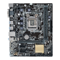
Asus B150M-A D3 Specifications

General IconGeneral
Form FactorMicro ATX
ChipsetIntel B150
SocketLGA 1151
Memory TypeDDR3
Memory Slots4
Maximum Memory64GB
PCIe x16 Slots1
PCIe x1 Slots2
SATA Ports6 x SATA 6Gb/s
AudioRealtek ALC887 8-Channel High Definition Audio CODEC
USB 2.0 Ports6
LANRealtek RTL8111H Gigabit LAN
Video OutputsVGA, HDMI

Related product manuals